Appendices
Appendix C: Electricity & Electronics Basics for Electronic Musicians
The following section is a simplified explanation of the properties and measurement standards of electricity, applicable to sound synthesis, audio principles and studio practice. The discussion will focus on current electricity, which is what is normally at play in the studio (aside from some annoying pops caused by static electricity when you touch your gear on a dry winter’s day).
Below that is a table of common electronic components and circuit diagrams, and brief explanations of how they work. Electronic musicians may wish to design their own physical interfaces, robotics, or visual displays using simple-to-understand kits and hardware. A very common type of programmable processor board or wearables for this is the Arduino family of devices, with tons of tutorials and videos about how to design your own devices that can act interactively with programs like Max, SuperCollider, Kyma, and Ableton Live. A company called Sparkfun not only sells much of this gear and the necessary components, but also has extensive tutorials on how to use and understand them.
Links to a few of the many more extensive tutorials and suppliers will be provided at the bottom of the page.
Electricity
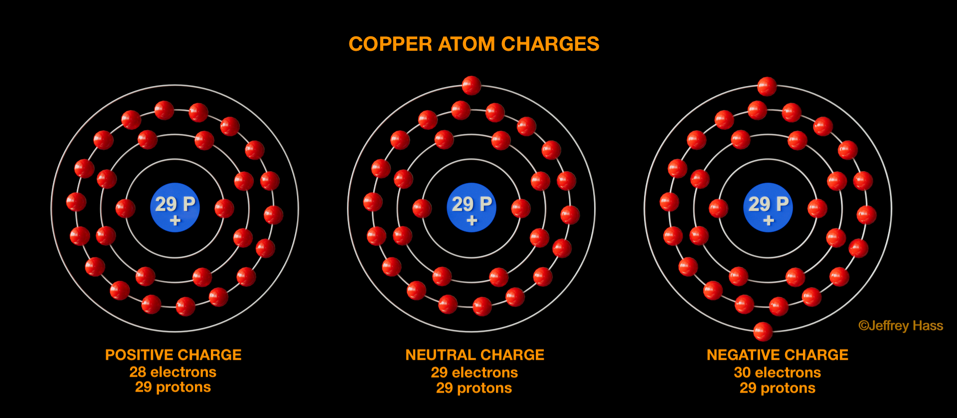
Electricity can be defined as the flow of electrical charge through matter. An atom will have negatively charged electrons (-), positively charged protons (+), and uncharged neutrons (which we don’t care about at the moment). A proton carries an equal and opposite charge to an electron. If an atom has an equal number of electrons and protons, its charge is said to be electrically neutral. However, if it has more protons than electrons, it is said to be positively charged, and if it has more electrons than protons, it is negatively charged, as illustrated below.
Charged particles exert a force across space in what is called an electric field. Like charges (-/- or +/+) repel, and unlike charges (-/+) attract. This is called electrostatic force, described by Coulumb’s Law.
In an electrical current through a conductive material, such as copper, which gives up its outer electron easily, negatively charged electrons (-) from the atom’s outer valence shell are pulled toward or are pushed from copper atom to atom. There are also loose or free electrons just hanging out, bouncing randomly between atoms and each other until an electrical force is applied. Electrons are referred to as the charge carriers. When an excess electron jumps onto a copper atom, its repulsive force causes another electron to be freed and jump off to eventually attach to a nearby atom, and so forth, setting up an electrical flow or current. The free electrons procede similarly, not bouncing into each other, but repelling other electrons via the like-charge electrostatic force. A free electron may also be attracted or pulled in by an electron-deficient positively charged atom, as simplistically demonstrated by the video below. The forceful movement of these charge carriers creates an electromagnetic field around the conductor.
click video image to play/pause
As with the air molecules of a sound wave, the individual electrons don’t move very far, but convey their energy to the next atom to which they attach or to other free electrons they repel. While the overall current moves very quickly with energy conveyed from charge to charge, the speed at which an individual electron moves is called its drift velocity, and that can be quite slow. For example in 12-gauge copper wire with a 10 amp DC current, electrons are moving only a little over an inch per hour.
In an electrical circuit, which is a loop designed to carry and make use of electrical current, the flow of electrons proceeds in one direction or the other (direct current or DC) or alternates between them (alternating current or AC), motivated by the differential of potential charges at the beginning and end of the circuit. In AC current, the electrons, which are constantly switching direction hardly move far from their origin at all.
An excellent question then might be, what direction does electricity move in? Unfortunately, there is a less than excellent answer. Benjamin Franklin, who may have coined the terms positive and negative charge in static and current electricity posited that electrical current moves from positive to negative. So for a wire attached to both poles of a battery, his thinking was the electrical charge would move from the positive terminal to the negative terminal. More recently, the concept of current direction is determined by a positive test charge (a conceptual charge with an infinitesimal positive charge) and which direction that would likely move in an electrical field, and the answer would still be from positive to negative. So positive to negative flow is called conventional current. Conventional current is how electrical engineers and others design electronic circuits. However, as we saw above, the negatively charged electrons move towards areas of electron deficits or holes, such as a positively charged, electron-deprived copper atom. So electron flow moves opposite conventional current, from negative to positive. Go figure.
Important Electricity Measurements
This section will focus on four key characteristics of electricity:
Voltage, measured in volts
Current, measured in amperes (or just amps)
Resistance, measured in ohms
Power, measured in watts
Voltage (V), named after Italian physicist/chemist Alessandro Volta, is a measurement of the potential amount of energy differential or charge between two points in a circuit. Technically, a volt is defined as the quantity of potential difference between two points that will impart one joule per coulomb of charge that passes through it. Less technically, it is the potential energy differential between two points of a conductor when a current of one amp imparts one watt. It is traditionally (albeit imperfectly) illustrated by a tank of water, or in our case spheres, with a hose or other conduit at the bottom. Looking at the video example below, the number of spheres represents the amount of charge, the downward pressure imparted by the number of spheres reacting to gravity represents the voltage, the rate of flow represents the amount of current or amps, and any narrowing to impede or slow down the flow of spheres represents resistance or ohms.
click video image to play/pause
In the video demonstration above, the container on the left with the red spheres begins with a higher amount of charge than the container on the right with the blue spheres. As the video plays, the initial pressure exerted at the end of the conduit, representing voltage, is greater for the container with the initial higher charge and they move with greater force and in greater number. As the spheres begin to run out, meaning there is less charge differential between the container and the ground, the pressure at the end of the conduit begins to drop. This is not dissimilar to your battery running out of juice as the differential between the poles drops with use.
Amperes (amps, amperage), named after French physicist/mathematician André-Marie Ampère, is traditionally represented in equations by the letter I. It is a measure of current, or the amount of charge flowing through a conductor per unit of time. Technically, 1 amp is defined as 6.241*1018 electrons (the definition of 1 coloumb) passing through a point in a circuit per second. However, for the non-technical, using the video above, you can surmise that the amount of charge initially passing through the two conduits are different. The red spheres, with the higher initial voltage, are passing through at a much higher rate than the blue spheres, and so would be said to represent higher amperage. Because the two conduits have exactly the same narrowing, representing equal resistance, it is clear that the greater amount of pressure in volts imparts a greater amount of current in amps. All else being equal, the greater the pressure, the greater the current.
Ohms (R or Ω), named after German physicist/mathematician Georg Ohm, is a measure of electrical resistance. All materials that carry electrical current will impede its flow to some degree with the possible exception of superconductors. This resistance normally converts some of the electrical energy into heat energy, as I am sure you have experienced when touching a warm wire or wall transformer or toaster. Circuit components specifically designed to reduce the amount of current are non-surprisingly called resistors, and the amount of reduction they provide are specified in ohms, often followed by the omega (Ω) symbol, though still pronounced “ohm.”

It should be noted that even the conducting wires themselves have some degree of resistance, some more than others–and the greater the distance they span, the greater the total resistance.
One ohm is defined as the amount of resistance required to limit one volt to producing one amp between two points in a circuit.
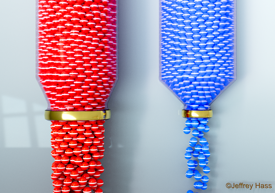
The image above illustrates by analogy, again using spheres, that given an equal amount of pressure (voltage), more resistance, illustrated by the greater narrowing of the container on the right, results in a decrease in current (amps). Hence fewer spheres or a lesser amount of charge is flowing.
Ohm's Law
One of the most famous equations used in electrical studies is Ohm’s Law, published by Ohm in 1827. It describes the relationship between voltage, current and resistance. Because one ohm is defined at the amount of resistance required to limit one volt to producing one amp between two points in a circuit, this allows us to use Ohm’s Law to calculate the relationship between volts (V), current in amps (I) and resistance in ohms (R) for direct current (DC) at a constant temperature as follows:
| by potential difference in volts |
by current in amps | by resistance in ohms |
||
| OR |  |
OR |  |


Using the above definition of 1 ohm, that would mean that:
 or
or ![]()
Accordingly, if we had a circuit powered by 1V with 1 Ω resistance, we would expect 1A of current. However, if we doubled the resistance, using A = 1V/2 Ω, we would get 0.5A, or half the current; doubling the resistance halves the current if the voltage remains constant.
What about alternating current (AC) circuits? After all, that is what powers out house, and electronic musicians may run their AC audio signals through analog mixing board faders, a source of variable resistance. Due to the rising and falling of the current, an additional impediment to the current exists in addition to resistance, referred to as reactance. The combination of resistance and reactance is called impedance, and is usually given the letter Z in formulas and specifications. For AC circuits, Z may be substituted for R in the Ohm’s Law formulas above. So for example, Z=V/I and V=I*Z. Impedance in circuits is still represented by the Ω symbol.
Ohm’s Law does break down in certain circumstances, such as the near-zero resistance of a superconductor, where it might imply infinite voltage has zero current. But there are also a class of far more common “non-ohmic” electrical components, such as LED’s and diodes that induce non-linear voltage drops that require different calculations. But for the most part, Ohm’s Law is extremely useful to know for circuit design and evaluation calculations.
Watts (W), named after steam engine pioneer James Watt, is a measurement of power. As discussed in the acoustics section of this text, power is the rate at which energy is produced or transferred. Technically, a watt is defined as the measurement of one joule per second (J/s). But a more useful equivalent for us would be that power (P) in a circuit, measured in watts, is equivalent to its voltage x its amps, or:

Here’s a practical example. If you live in a house or apartment in a country with ~120 volt AC electrical circuits, and you find the breaker box, you are likely to see circuit breakers listed as 15 amps or 20 amps. Using the formula above as W = V * A, a 120 volt, 15 amp circuit should be able to handle 1800 watts of equipment or appliances running at once (hair dryers, toasters, etc.), but a 20 amp circuit should handle 2400 watts of electrical draw. If you concurrently use over that combined wattage draw on a circuit, the breaker should trip before you damage the wiring or set your house on fire.
Ohm's Law + Power Calculator
Check the TWO values you wish to enter to calculate the others
Thank you Roberto Lo Giacco for the calculator code.
Power Ratings in watts and ohms
Often in electronic specifications, like those for a resistor or a loudspeaker, you will see power ratings (or power handling ratings), listed in terms of watts into resistance or impedance. For example, a loudspeaker, which is electrically inefficient, may list one of its power-handling ratings as being able to continuously handle 1000W into an 8 Ω load impedance (since speakers handle AC audio signals, they are often specified using a 1kHz sine wave), which is the thermal limit before the voice coil may generate so much heat it fries and fuses to the magnet that encloses it. Most small resistors, as pictured above, can handle 1/8 to 1/2 of a watt (indicated by one of the colored bands). But larger power resistors can handle much greater power, and as the example below shows, the resistor’s rating is displayed in both watts and ohms.
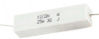
To calculate both power and resistance, a little substitution of Ohm’s Law terms gives us:
| by power with volts |
by power with current (in amps) | by volts |
||
 |
OR | OR |  |


Using the formula above, a speaker peak power rating of 1000W into an 8Ω load can handle approximately 90 volts AC maximum safely, so 90V = sq root (1000W * 8 Ω). The 25W 3Ω resistor pictured above can handle a maximum of 14.1V.
Common Electronics Components and Their Function
| The chart below lists some of the most common electronics components, along with a representative image, their schematic symbol and a brief description of their function. | |||
|---|---|---|---|
| Component | Image | Schematic Symbol |
Description |
| resistor (a) variable resistor (b) potentiometer (c) |
 |
 |
Resistors, as mentioned above, are used in circuits to reduce current, voltage and power by converting some of their electrical energy input into heat. They have several designs, with most consisting of a spiral helix of less-efficiently conducting material such as carbon film or powder, or thin wire densely wrapped around a non-conductive core. Lower power resistors, handling ½ watt or less, are coated in a plastic insulator, and their resistance in ohms is indicated by a series of colored bands (click to see chart). Some also feature a band that indicates their possible resistive deviation/tolerance from their spec. A class of resistors called variable, rheostats and potentiometers are able to vary their resistance through physical action, such as the volume knob on a radio, or the channel faders on a mixing board. Some special resistors that are of particular use to electronic musicians making their own data-driven devices are photo-resistors and strain gauges that change their resistance with light or physical bending. The circuit discussion below will describe how connecting resistors in parallel or series makes a difference to the combined total resistance of a circuit. Resistance is measured in ohms (Ω). |
| capacitor | 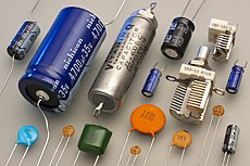 |
 |
A capacitor stores an electrical field charge across two conductive plates usually separated by a non-conductive dielectric material or a vacuum. When the plates are charged by an electrical differential applied across them in a circuit, forming an opposing positive or negative charge on each plate, a capacitor can quickly discharge its charge should the current cease or drop. In this way, it can serve to smooth instabilities in a current from a power supply (acting like a computer's buffer), or it can suddenly provide instant power for the start-up of a device. Capacitors serve many other functions as well, such as blocking DC current while allowing AC current to pass or maintaining an on(1) or off(0) state in computer DRAM memory. Variable capacitors can be used to tune looping circuits, such as those used in audio oscillators, filters, blinking lights and radio tuners and these components often have multiple interleaving plates (see in image) that can be adjusted with a knob. Capacitors were previously called condensers, with the nomenclature still remaining for condenser microphones. Capacitance is measured in farads (F). |
| diode light emitting diode (LED) |
 |
 diode diode |
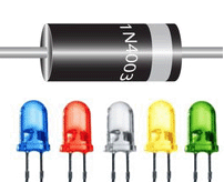
Diodes are inline electronic components that act like a one-way street for electric current. Under most circumstances in a circuit, a diode passes current in one direction (the direction towards the narrow painted band, or the schematic arrow from the anode to the cathode) but not in the other. Because of their tremendous usefulness, diodes, made primarily of semiconducting silicon, appear in almost all complex electronic circuits. They are used to convert AC voltage into DC voltage by means of a 4-diode diamond-shaped bridge rectifier circuit. They can also be used in computer logic circuits and much more. As mentioned above when discussing the total resistance values of a circuit, diodes impart a small voltage drop, or a little resistance, in the direction the current is traveling in—the amount of drop is dependent on temperature, though non-linear, so they can be used for temperature sensing. There is a small threshold of voltage required before the diode begins to pass any current. Diodes should provide infinite resistance for current traveling against the pass-through direction. However, if that voltage exceeds a certain level called the breakdown voltage, the diode will pass it in the “wrong” direction with little resistance, which is also useful under some circumstances. Diodes are specified with many characteristics, but importantly their amount of forward voltage drop and the reverse breakdown voltage threshold. Light emitting diodes, or LED’s, are in common usage now, including home lighting. Like the normal diode above, they pass current in only one direction. But in addition, they emit photons at various colors and intensities. In the studio, LED’s can be useful for confirming the on/off state of a device or in the circuit design of a homemade data-driven interface both for performance and troubleshooting. Their instant-on light makes them useful for level indicators on mixing boards. And their ability to emit invisible light in the infrared makes them perfect for remote controls, one of their original applications. |
| transformer | 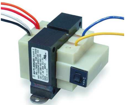 |
 |
Transformers are used to do what the name implies, transform electricity. They are used in everything from lowering the voltage of electricity from hundreds of thousands of volts AC that efficiently brings power to your neighborhood from a power plant through high tension power lines to the household current (110-220V AC) you are using now. Or the “wall-wart” transformer you likely have many of to charge your cell phone or power small electronic devices. If you read the label of your wall-wart, it will tell you it is reducing the household voltage from 120 V to something like 12 V, likely along with a change in amperage as well. Transformers are often used in conjunction with other circuit parts to not only reduce voltage, but to convert it to low power DC for use in most electronic devices, something your wall-wart may do through a switching circuit. Transformers are a key component of a computer power supply. They are used ubiquitously in audio circuits for impedance matching of mics, amps and loudspeakers, for balancing lines, isolating circuits and much more. If you look at the schematic symbol on the left, you can see that a transformer has three main components. A primary coil of wire (called windings) where the original power is applied, a secondary coil (not in any way electrically attached to the primary coil), and a core, which may or may not be made out of solid iron or special laminated steel. When current is applied to the primary coil, it creates an electromagnetic field which is efficiently directed to the secondary coil by means of the electromagnetic properties of the core. The secondary coil’s output is then directed to the circuits or devices one wishes to power. So by means of induction or electromotive force, the magnetic field sets up a similar current in the secondary coil. If both coils had an identical number of windings, the amount of voltage induced in the secondary coil would be close to that of the primary coil (in audio, these are used as isolation transformers since there is no direct connection between coils). However, the most-used purpose of the transformer is to transform voltage, and that is accomplished by having a different number of windings in the secondary coil. If the secondary coil has more windings than the primary coil, the voltage output will be increased–that is called a step-up transformer. If the secondary coil has fewer windings, then the voltage will be reduced, and that is called a step-down transformer. The formula for calculating the output voltage of an ideal transformer (i.e. one with no current loss) is Vs = Vp * Ns / Np where Vs is the secondary voltage, Vp is the primary voltage, Ns is the number of secondary windings, and Np is the number of primary windings. So to reduce 120V to 12V, a transformer needs to have 10 times as many windings on the primary coil than the secondary coil. In general, power (in watts) stays constant, so without other factors, using Ohm’s Law for wattage above P=V*I, if one decreases voltage, one increases current (amps) and visa versa. You may see transformers that have many wires coming out of them, providing different voltages and even phases. That is because in addition or in place of taking voltage only from the two ends of the secondary coil, additional taps can be added, taking current from the middle or elsewhere on the coil that have various voltages depending on their position. A center tap transformer takes the voltage from either side of the secondary coil and a wire attached to the middle of it. If 120V AC is applied to the transformer, each half of the secondary coil will produce 60V AC, with one of the pair being 180° out of phase with the other. This transformer design is actually used to create balanced lines in audio devices such as mixers. Finally, many transformers have more than a one secondary coil placed along the longer primary one. |
| transistor | 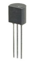 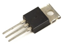 |
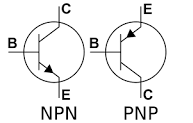 |
A transistor is a type of semiconductor used to amplify or switch an electronic or digital signal, or to control power transfer. Its properties allow it to act similarly to both diodes and variable resistors. Invented at Bell Labs in 1947, it has almost completely replaced vacuum tubes that provided the same function (to the displeasure of some vintage audio gear lovers who claim it’s not the same as it lacks the warm tube distortion qualities). Unlike vacuum tubes, however, the mostly silicon, occasionally germanium material generates a fraction of the heat, has a much longer lifespan and endures greater physical, though not electrical, abuse. It is also much smaller in size, starting with the game-changing MOSFET design invented in 1963. Computer IC chip components, such as memory, CPUs or GPUs may have billions or trillions of transistors on a single chip. For example, in 2022, Apple's M1 Ultra "SoC or system-on-a-chip" contains 114 billion transistors, in a density of 135 million of them per square millimeter. Like the earlier triode vacuum tube, a small control “bias” current, such as a low voltage audio signal, is passed into one of the normally three leads to control or modulate how much of a higher voltage source is allowed to pass through the transistor by varying the conductivity of the silicon substrate. This provides a linear amplification function, where the transistor’s higher-power output mimics the shape of the lower-power signal input. Similar to operating a water faucet, a small adjustment of the faucet valve knob controls the intensity of the flow of water from your supply line to your sink (why the British called vacuum tubes “valves”). Transistors can also function as switches for use in high-voltage switching power supplies, switching audio amplifiers, or low voltage computer logic gates. There are two most common types of transistors, though with many variations. One is called a bipolar junction transistor (BJT) design (pictured left and in the schematic), that contains a base, collector and emitter. The other called a field-effect transistor (FET) design (pictured right) with a gate, source and drain. FETs use either electrons or the deficit of electrons (called electron holes) as the charge carrier for the gate, which determines how much of the opposite unipolar charge can flow from the source to the drain in most cases (follow the FET link for a way more thorough explanation). For the BJT, a smaller current applied to the base will determine how much current can flow between the higher-voltage and opposite polarity emitter and collector terminals. A small threshold of current is required, usually around .5-.7V, to have the transistor begin to pass any of the higher current at all. The most numerous transistors by far (as in 99%) are of the MOS field effect (MOSFET) type, which are incorporated in huge numbers into integrated circuit components for both analog and digital use as mentioned above. Both transistor types are classified as being either NPN (negative-positive-negative) or PNP (positive-negative-positive), with the base biasing polarity being the middle letter. This is accomplished by having three “stripes” of added materials to the silicon that give the stripes either a negative or positive (electron hole) charge, two of one charge, one of the other. MOSFETs may have a fourth connection called a substrate which acts as a ground for one layer of the material and is often used to "turn on" the transistor. High-voltage MOSFETs, like the one picture here, often have a hole so they may be screwed onto a heat sink to dissipate the heat before it damages the chip. |
| printed circuit board |  |
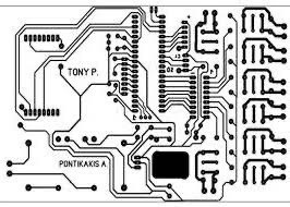 |
Most electronic devices utilize one or more printed circuit boards or PCB’s to organize and connect their electrical components. The motherboard of the computer or phone you are reading this on is a PCB. Early electrical devices simply hand-wired or soldered components together, and later did so on metal electrical chassis, where tubes and other components sat in sockets or insulators on top, and all the other components were hand-wired below , with the metal providing a common ground (hopefully). Through the 1940’s and 50’s, developments led to actually painting or printing metallic circuit connections onto an insulating substrate, and this turned into the modern PCB boards of today. Very few circuits today require additional hand-wiring between components. PCB’s begin life as a wafer of a thin copper surface with fiberglass or other non-conductive material below. Some boards are two-sided and have copper on both sides. And some more modern boards are sandwiches of several alternating layers. Circuit patterns are either silk-screened or photo-transferred onto the copper, and the board is then etched to remove the non-conductive areas that were not covered by the screening. The board may then be further electroplated to add additional conductive metallic material on top of the copper circuit lines. And finally holes will be drilled for the electronic components to sit in. Some holes will conduct through to the other side, or wafer layers, some will not. The board will be cut to desired size and shape and the tabs may be silver or gold-plated for improved contact. While some boards may have electronic components added and even soldered by hand, the vast majority now are designed to be populated by robotic machines. Sockets for IC chips(see below) and other plug-in components will also be added at this stage. After that, a usually green solder mask is applied and the board is sent through a wave solder bath that mass solders the components to the lugs around the holes where the solder mask doesn’t exist. If you need to make repairs on a PCB, you may need to scrape off some of the solder mask to resolder components. |
| integrated circuit | 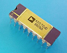 |
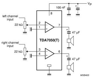 |
The integrated circuit (IC) has revolutionized electronics and computing by replacing entire circuit boards with a single, small component. Simple circuits, such as a digital clock, or indeed entire computers (system-on-a-chip, or SoC) can be contained in a single IC. Most PCB’s incorporate a number of IC’s. IC chips are usually made of silicon, some, like lasers, of gallium arsenide, where millions, even tens of billions of transistors can be etched onto something the size of a dime. Originally the transistors were the bipolar junction-type, but most IC’s now are exclusively MOSFETs (mostly of the low power CMOS type). IC's can be analog, digital, or both, like an A-to-D converter. They are typically either hard-wired into a PCB or are seated into a socket. Computer CPU's often have a hundred or more pins, so if you build your own computer, seating them into a motherboard socket without bending the pins is always a challenge. IC’s are created similarly to PCBs above, but on a much smaller scale, with the most valuable and complex being made in clean rooms, as even a spec of dust during manufacture can block a hundred transistors from being created. The circuit pattern is photographically transferred to a silicon or gallium arsenide wafer, then etched. The MOSFETs are then “doped” to produce their transistor properties. Jack Kilby of Texas Instruments, pioneers of the early digital pocket calculators, is credited with the first practical design in 1959, shortly improved to avoid the need for any additional wires (called monolithic) by Robert Noyce half a year later. IC's in audio use range widely from DSPs, to A/D (pictured left) or D/A converters, complete synthesizers, signal amplifiers (pictured in the schematic), op-amps, digital clocks, voltage regulators and much more. A whole subfield of electronic music grew up around hacking IC's from toys like the Speak and Spell's voice synthesizer. If you are shopping for the latest and greatest computer CPU, you will start reading about how dense the components and circuit connections can be, and the special substrates they are developing. Moore’s Law predicted a doubling of the number of transistors in an IC every two years. However, due to the necessary heat dissipation and simple physics breakdown at the nanoscale molecular level now that components are getting so close, other atomic and subatomic strategies are being explored, even testing how to exploit the spin of electrons to bypass the transistor limit. |
| breadboard |  |
N/A | A breadboard is often used for prototyping or self-designing of circuits. The hole spacing matches the pin configurations of many non-flexible components, such as certain IC's and transistors (see Sparkfun image left). Rows connect across and additional connections are made by jumper wires. The rows with the red and blue stripes are traditionally used to supply power to the circuit from a power supply or battery. They are available in a wide variety of sizes. If one were to create some sort of homemade interface, a breadboard would be the likely choice for building the circuit, perhaps connected to an Arduino or other higher-level device or computer as well. |
resistor (a) variable resistor (b) potentiometer (c)


Resistors, as mentioned above, are used in circuits to reduce current, voltage and power by converting some of their electrical energy input into heat. They have several designs, with most consisting of a spiral helix of less-efficiently conducting material such as carbon film or powder, or thin wire densely wrapped around a non-conductive core. Lower power resistors, handling ½ watt or less, are coated in a plastic insulator, and their resistance in ohms is indicated by a series of colored bands (click to see chart). Some also feature a band that indicates their possible resistive deviation/tolerance from their spec. A class of resistors called variable, rheostats and potentiometers are able to vary their resistance through physical action, such as the volume knob on a radio, or the channel faders on a mixing board. Some special resistors that are of particular use to electronic musicians making their own data-driven devices are photo-resistors and strain gauges that change their resistance with light or physical bending. The circuit discussion below will describe how connecting resistors in parallel or series makes a difference to the combined total resistance of a circuit. Resistance is measured in ohms (Ω).
capacitor


A capacitor stores an electrical field charge across two conductive plates usually separated by a non-conductive dielectric material or a vacuum. When the plates are charged by an electrical differential applied across them in a circuit, forming an opposing positive or negative charge on each plate, a capacitor can quickly discharge its charge should the current cease or drop. In this way, it can serve to smooth instabilities in a current from a power supply (acting like a computer's buffer), or it can suddenly provide instant power for the start-up of a device. Capacitors serve many other functions as well, such as blocking DC current while allowing AC current to pass or maintaining an on(1) or off(0) state in computer DRAM memory. Variable capacitors can be used to tune looping circuits, such as those used in audio oscillators, filters, blinking lights and radio tuners and these components often have multiple interleaving plates (see in image) that can be adjusted with a knob. Capacitors were previously called condensers, with the nomenclature still remaining for condenser microphones. Capacitance is measured in farads (F).
diode and light emitting diode (LED)

 diode
diode
![]() LED
LED
Diodes are inline electronic components that act like a one-way street for electric current. Under most circumstances in a circuit, a diode passes current in one direction (the direction towards the narrow painted band, or the schematic arrow from the anode to the cathode) but not in the other. Because of their tremendous usefulness, diodes, made primarily of semiconducting silicon, appear in almost all complex electronic circuits. They are used to convert AC voltage into DC voltage by means of a 4-diode diamond-shaped bridge rectifier circuit. They can also be used in computer logic circuits and much more. As mentioned above when discussing the total resistance values of a circuit, diodes impart a small voltage drop, or a little resistance, in the direction the current is traveling in—the amount of drop is dependent on temperature, though non-linear, so they can be used for temperature sensing. There is a small threshold of voltage required before the diode begins to pass any current. Diodes should provide infinite resistance for current traveling against the pass-through direction. However, if that voltage exceeds a certain level called the breakdown voltage, the diode will pass it in the “wrong” direction with little resistance, which is also useful under some circumstances. Diodes are specified with many characteristics, but importantly their amount of forward voltage drop and the reverse breakdown voltage threshold.
Light emitting diodes, or LED’s, are in common usage now, including home lighting. Like the normal diode above, they pass current in only one direction. But in addition, they emit photons at various colors and intensities. In the studio, LED’s can be useful for confirming the on/off state of a device or in the circuit design of a homemade data-driven interface both for performance and troubleshooting. Their instant-on light makes them useful for level indicators on mixing boards. And their ability to emit invisible light in the infrared makes them perfect for remote controls, one of their original applications.
transformer


Transformers are used to do what the name implies, transform electricity. They are used in everything from lowering the voltage of electricity from hundreds of thousands of volts AC that efficiently brings power to your neighborhood from a power plant through high tension power lines to the household current (110-220V AC) you are using now. Or the “wall-wart” transformer you likely have many of to charge your cell phone or power small electronic devices. If you read the label of your wall-wart, it will tell you it is reducing the household voltage from 120 V to something like 12 V, likely along with a change in amperage as well. Transformers are often used in conjunction with other circuit parts to not only reduce voltage, but to convert it to low power DC for use in most electronic devices, something your wall-wart may do through a switching circuit. Transformers are a key component of a computer power supply. They are used ubiquitously in audio circuits for impedance matching of mics, amps and loudspeakers, for balancing lines, isolating circuits and much more.
If you look at the schematic symbol on the right, you can see that a transformer has three main components. A primary coil of wire (called windings) where the original power is applied, a secondary coil (not in any way electrically attached to the primary coil), and a core, which may or may not be made out of solid iron or special laminated steel. When current is applied to the primary coil, it creates an electromagnetic field which is efficiently directed to the secondary coil by means of the electromagnetic properties of the core. The secondary coil’s output is then directed to the circuits or devices one wishes to power. So by means of induction or electromotive force, the magnetic field sets up a similar current in the secondary coil. If both coils had an identical number of windings, the amount of voltage induced in the secondary coil would be close to that of the primary coil (in audio, these are used as isolation transformers since there is no direct connection between coils). However, the most-used purpose of the transformer is to transform voltage, and that is accomplished by having a different number of windings in the secondary coil. If the secondary coil has more windings than the primary coil, the voltage output will be increased–that is called a step-up transformer. If the secondary coil has fewer windings, then the voltage will be reduced, and that is called a step-down transformer. The formula for calculating the output voltage of an ideal transformer (i.e. one with no current loss) is Vs = Vp * Ns / Np where Vs is the secondary voltage, Vp is the primary voltage, Ns is the number of secondary windings, and Np is the number of primary windings. So to reduce 120V to 12V, a transformer needs to have 10 times as many windings on the primary coil than the secondary coil. In general, power (in watts) stays constant, so without other factors, using Ohm’s Law for wattage above P=V*I, if one decreases voltage, one increases current (amps) and visa versa.
You may see transformers that have many wires coming out of them, providing different voltages and even phases. That is because in addition or in place of taking voltage only from the two ends of the secondary coil, additional taps can be added, taking current from the middle or elsewhere on the coil that have various voltages depending on their position. A center tap transformer takes the voltage from either side of the secondary coil and a wire attached to the middle of it. If 120V AC is applied to the transformer, each half of the secondary coil will produce 60V AC, with one of the pair being 180° out of phase with the other. This transformer design is actually used to create balanced lines in audio devices such as mixers. Finally, many transformers have more than a one secondary coil placed along the longer primary one.
transistor


A transistor is a type of semiconductor used to amplify or switch an electronic or digital signal, or to control power transfer. Its properties allow it to act similarly to both diodes and variable resistors. Invented at Bell Labs in 1947, it has almost completely replaced vacuum tubes that provided the same function (to the displeasure of some vintage audio gear lovers who claim it’s not the same as it lacks the warm tube distortion qualities). Unlike vacuum tubes, however, the mostly silicon, occasionally germanium material generates a fraction of the heat, has a much longer lifespan and endures greater physical, though not electrical, abuse. It is also much smaller in size, starting with the game-changing MOSFET design invented in 1963. Computer IC chip components, such as memory, CPUs or GPUs may have billions or trillions of transistors on a single chip. For example, in 2022, Apple's M1 Ultra "SoC or system-on-a-chip" contains 114 billion transistors, in a density of 135 million of them per square millimeter.
Like the earlier triode vacuum tube, a small control “bias” current, such as a low voltage audio signal, is passed into one of the normally three leads to control or modulate how much of a higher voltage source is allowed to pass through the transistor by varying the conductivity of the silicon substrate. This provides a linear amplification function, where the transistor’s higher-power output mimics the shape of the lower-power signal input. Similar to operating a water faucet, a small adjustment of the faucet valve knob controls the intensity of the flow of water from your supply line to your sink (why the British called vacuum tubes “valves”).
Transistors can also function as switches for use in high-voltage switching power supplies, switching audio amplifiers, or low voltage computer logic gates. There are two most common types of transistors, though with many variations. One is called a bipolar junction transistor (BJT) design (pictured left and in the schematic), that contains a base, collector and emitter. The other called a field-effect transistor (FET) design (pictured right) with a gate, source and drain. FETs use either electrons or the deficit of electrons (called electron holes) as the charge carrier for the gate, which determines how much of the opposite unipolar charge can flow from the source to the drain in most cases (follow the FET link for a way more thorough explanation). For the BJT, a smaller current applied to the base will determine how much current can flow between the higher-voltage and opposite polarity emitter and collector terminals. A small threshold of current is required, usually around .5-.7V, to have the transistor begin to pass any of the higher current at all. The most numerous transistors by far (as in 99%) are of the MOS field effect (MOSFET) type, which are incorporated in huge numbers into integrated circuit components for both analog and digital use as mentioned above.
Both transistor types are classified as being either NPN (negative-positive-negative) or PNP (positive-negative-positive), with the base biasing polarity being the middle letter. This is accomplished by having three “stripes” of added materials to the silicon that give the stripes either a negative or positive (electron hole) charge, two of one charge, one of the other. MOSFETs may have a fourth connection called a substrate which acts as a ground for one layer of the material and is often used to "turn on" the transistor. High-voltage MOSFETs, like the one picture here, often have a hole so they may be screwed onto a heat sink to dissipate the heat before it damages the chip.
printed circuit board


Most electronic devices utilize one or more printed circuit boards or PCB’s to organize and connect their electrical components. The motherboard of the computer or phone you are reading this on is a PCB. Early electrical devices simply hand-wired or soldered components together, and later did so on metal electrical chassis, where tubes and other components sat in sockets or insulators on top, and all the other components were hand-wired below , with the metal providing a common ground (hopefully). Through the 1940’s and 50’s, developments led to actually painting or printing metallic circuit connections onto an insulating substrate, and this turned into the modern PCB boards of today. Very few circuits today require additional hand-wiring between components.
PCB’s begin life as a wafer of a thin copper surface with fiberglass or other non-conductive material below. Some boards are two-sided and have copper on both sides. And some more modern boards are sandwiches of several alternating layers. Circuit patterns are either silk-screened or photo-transferred onto the copper, and the board is then etched to remove the non-conductive areas that were not covered by the screening. The board may then be further electroplated to add additional conductive metallic material on top of the copper circuit lines. And finally holes will be drilled for the electronic components to sit in. Some holes will conduct through to the other side, or wafer layers, some will not. The board will be cut to desired size and shape and the tabs may be silver or gold-plated for improved contact. While some boards may have electronic components added and even soldered by hand, the vast majority now are designed to be populated by robotic machines. Sockets for IC chips(see below) and other plug-in components will also be added at this stage. After that, a usually green solder mask is applied and the board is sent through a wave solder bath that mass solders the components to the lugs around the holes where the solder mask doesn’t exist. If you need to make repairs on a PCB, you may need to scrape off some of the solder mask to resolder components.
integrated circuit


The integrated circuit (IC) has revolutionized electronics and computing by replacing entire circuit boards with a single, small component. Simple circuits, such as a digital clock, or indeed entire computers (system-on-a-chip, or SoC) can be contained in a single IC. Most PCB’s incorporate a number of IC’s. IC chips are usually made of silicon, some, like lasers, of gallium arsenide, where millions, even tens of billions of transistors can be etched onto something the size of a dime. Originally the transistors were the bipolar junction-type, but most IC’s now are exclusively MOSFETs (mostly of the low power CMOS type). IC's can be analog, digital, or both, like an A-to-D converter. They are typically either hard-wired into a PCB or are seated into a socket. Computer CPU's often have a hundred or more pins, so if you build your own computer, seating them into a motherboard socket without bending the pins is always a challenge.
IC’s are created similarly to PCBs above, but on a much smaller scale, with the most valuable and complex being made in clean rooms, as even a spec of dust during manufacture can block a hundred transistors from being created. The circuit pattern is photographically transferred to a silicon or gallium arsenide wafer, then etched. The MOSFETs are then “doped” to produce their transistor properties. Jack Kilby of Texas Instruments, pioneers of the early digital pocket calculators, is credited with the first practical design in 1959, shortly improved to avoid the need for any additional wires (called monolithic) by Robert Noyce half a year later. IC's in audio use range widely from DSPs, to A/D (pictured left) or D/A converters, complete synthesizers, signal amplifiers (pictured in the schematic), op-amps, digital clocks, voltage regulators and much more. A whole subfield of electronic music grew up around hacking IC's from toys like the Speak and Spell's voice synthesizer.
If you are shopping for the latest and greatest computer CPU, you will start reading about how dense the components and circuit connections can be, and the special substrates they are developing. Moore’s Law predicted a doubling of the number of transistors in an IC every two years. However, due to the necessary heat dissipation and simple physics breakdown at the nanoscale molecular level now that components are getting so close, other atomic and subatomic strategies are being explored, even testing how to exploit the spin of electrons to bypass the transistor limit.breadboard

A breadboard is often used for prototyping or self-designing of circuits. The hole spacing matches the pin configurations of many non-flexible components, such as certain IC's and transistors (see Sparkfun image left). Rows connect across and additional connections are made by jumper wires. The rows with the red and blue stripes are traditionally used to supply power to the circuit from a power supply or battery. They are available in a wide variety of sizes. If one were to create some sort of homemade interface, a breadboard would be the likely choice for building the circuit, perhaps connected to an Arduino or other higher-level device or computer as well.
The majority of images in this table are attributable to Wikicommons
Circuits: Series and Parallel
Below is a very brief introduction to the two basic circuit types, series and parallel. If you get nothing more out of this short explanation, it will be to buy holiday lights that are wired in parallel, not series. A circuit in electricity is one in which electricity flows from a beginning to an end in a circular path from a source. For example, a wire whose ends are connected to both poles of a battery forms a circuit (and without intervening components will quickly drain your battery).
A series circuit is one in which components are connected end to end and provide only one path for electricity to flow through, as indicated in the diagram below.
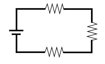
If one had a series circuit of only resistors, to calculate the total resistance of the circuit, one would simply sum the resistance value of each resistor, so:
Rtotal = R1 + R2 + R3…Rn
If one component in a series circuit, such as a light bulb fails and no longer passes current, the circuit ceases to function at all.
In a parallel circuit, the current is split to travel through components taking multiple paths, as shown below. In this case, the total resistance of the circuit is calculated as:
1/Rtotal = 1/R1 + 1/R2 + 1/R3…1/Rn
If these were light bulbs instead of resistors, if one bulb failed, the others would still operate.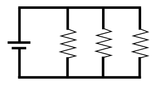
Some, if not most, real-life complex circuits are a hybrid series and parallel arrangement, where some current passes through certain components, but all current passes through others
Many tutorials on the web provide a good introduction to series and parallel circuits, but we really enjoyed this one from Sparkfun.
More Detailed Articles and Videos
Sparkfun: What is Electricity
Sparkfun:
Voltage-Current-Resistance and Ohm's Law
Sparkfun:
Electric Power
Hyperphysics: Electricity and Magnetism (more technical, but excellent!)
History of Electricity and Magnetism Discoveries (BBC Youtube video: Shock and Awe with Jim Al-Khalili). Simply amazing if you enjoy this sort of thing.
Suppliers
Mouser Electronics just about everything you can imagine electronic...sensors, components, ICs, Arduinos, etc.
Sparkfun sensors, components, ICs, kits, Arduinos (plus their own modified designs), sensors, geared towards creative use and users, and many tutorials
Avnet Electronics similar to Mouser, huge inventory of just about everything geared towards professionals
Digikey Electronics also similar to Mouser and Avnet
Many more can be found with a web search