Chapter Two: Studio Gear
5. Signal Processing (Effects)
Below are some basic signal processing effects found in most studios and home audio editing software. More than likely, composers will now be using virtual digital effects as plug-ins in a DAW and not sending signals out to outboard effects devices. But these concepts apply to both.
Wet/Dry Mix:
Most signal processing units or software have a wet/dry mix to set the proportion of mix between the source (dry) and effected (wet) signals. For effects like a single echo, you will definitely want to hear both the dry and wet sound. For an effect like pitch shift, a totally wet sound will output only the new pitch and not the original. If you are using effects sends to send to a separate effect channel, as opposed to having your effect inline in the input channel, you will more often than not leave the wet/dry mix on the effect at 100% wet, since you can control the ratio from your channel's effect send pot (see Channel Aux Sends).
Latency: When combining pre-recorded tracks with live sound input that is routed through digital plug-ins or outboard digital effects, an undesirable phenomenon called latency may occur. Latency is caused by the way effects are processed through a buffer, which collects audio samples before processing them. Usually this is small and unnoticeable delay.. Some DAW programs, like Digital Performer, have automatic latency compensation...even though you may hear a slight delay, it will correct it when the track is recorded, but of course that won't help for live processed performance. A possible fix for excessive latency would be to reduce the effect buffer size or the DAW buffer size, but this is not always possible, and when it is, too small a buffer can cause different problems.
Reverb
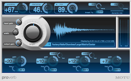
Digital Performer Proverb Convolution Reverb Plugin
As discussed in the previous Acoustics chapter, reverberation or reverb is the prolongation of sound waves via reflection and refraction. While it may occur continuously during the course of a sonic event, it is most noticeable and measurable after the source impulse has ended. Reverb is distinguishable from simple multiple echoes, such as shouting into a canyon might produce, by the rapid build-up of reflective density to a point the individual reflections are indistinguishable. Reverb is created naturally in an enclosed environment, but can also be created artificially through electronic means. A more extensive description of natural and artificial reverb and the different types can be found here. Some items are repeated below.
A few practical tips for reverb use: As with the delay effect below, or in fact anything that extends the sound beyond the end of a sound file, it is extremely important NOT to cut off the soft ending of the reverb (called the reverb tail) when editing or bouncing. It is recommended you extend your bounce selection well beyond the audible end of the reverb and then trim back after bouncing, aided by greatly enlarging the waveform display and increasing monitoring level. What might not be an audible untimely end to your reverb tail in the studio may be very apparent in a concert hall. In addition, the composer is encouraged to use reverb sparingly, if at all, on individual audio tracks, but rather to use effects sends to send the source channels to a single master reverb auxiliary channel. Reverb tends to multiply exponentially, and once bounced, is virtually impossible to reduce once better judgment sets in. The primary reason to have reverb on individual tracks would be if the reverb settings were to be greatly differentiated from other tracks. It is recommended you choose stereo reverb plugins for both mono and stereo tracks, particularly since some reverbs have stereo differentiation. And finally, for effect chains, it is most common to put the reverb effect last.
Controls: reverb time (or impulse response length for convolution reverb), pre-delay (time before onset of reverb), highpass filter (hpf), lowpass filter (lpf), stereo difference, diffusion, damping, color. Convolution reverbs, which use an impulse response (IR) files, encapsulate several of these parameters simply by choosing different impulse responses.
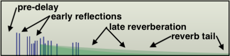
ANATOMY OF REVERBERATION
Image created with Mark of the Unicorn's Digital Performer eVerb plug-in.A Few Definitions for Less Obvious Reverb Controls
A more detailed discussion of DSP-related audio plug-ins will appear later, but here is a good place to discuss some of the more esoteric controls you are likely to encounter with artificial reverbs.
Pre-delay, as the name implies, is a gap in time before the reverb reflections begin to sound. It gives the listener a cue as to the size of an artificial environment. Greater delay before the early reflections sound indicate a larger environment.
Diffusion, often a setting on reverb units, refers to the phase coherence of sound reflecting off a surface. For a perfectly reflective surface, sound will reflect with one coherent phase. However, less perfect surfaces (or deliberately imperfect surfaces, such as acoustic diffuser treatments) will return the incident wave to the listener with multiple reflections out of phase with each other, much as a prism or a frosted light bulb would break light into component parts (think light diffuser). The acoustic result for the composer is that a higher setting for reverb diffusion shortens the space between the early reflections and creates a denser sound early on, with more of the comb effect mentioned above. With diffusion set to zero, early reflections may sound discreet and separate, more like echoes depending on their spacing and amplitude settings.
Damping, another parameter often found on reverb units, controls higher frequencies spreading and dying out more quickly than lower frequencies, something we use as an aural cue for the size of a space in addition to the first return of reflections. Damping also helps the user to zero on the desired impression of room materials, such as curtains and carpets, which absorb more high frequency reflections than low. A concert hall or football field will have a higher degree of damping than a small studio with hard, reflective walls. In the third example below with 25% damping, listen for the high frequencies to decay more quickly.
Color will regenerate some of the initial reflection, where room modes or "color" are most discernible, into the late reverb, extending the initial room resonance.
Length parameters for convolution reverbs will allow the user to "stretch" or "shrink" the IR file to assist in avoiding troublesome resonance modes, particularly in the lower range, by effectively changing the size of the room to a small degree while still maintaining the basic character of the room.
For further explanations of common reverb controls, as well as tips on how to effectively use them, see Craig Anderton's excellent article on the subject.
Reverb Audio Examples (all stereo)
| Dry Signal | "Plate Reverb
Announcer Booth" 50% mix (subtle, compare to dry) |
Medium Room 95 ms pre-delay 50% mix |
Concert Hall (3 second impulse) 25% damping 50% mix |
|---|---|---|---|
Equalization (EQ)
An equalizer can boost or cut certain frequency ranges, in that they are comprised of a series of peak/notch audio filters. The two main types of equalizers are graphic EQ's and parametric EQ's. Equalization, as the name might imply, was originally designed to fix the frequency response flaws of an environment to create a more or less flat response to all frequencies after recording or during playback. In time, its use expanded to make things "better" than they once were (maybe heavier bass, or increased presence in the 2k-5k range). Additionally, EQ is used to create special effects and timbres, and may be used dynamically to alter timbre in realtime. Common errors include boosting everything, with no negative bands, or boosting a band so much, when a signal component hits it, it distorts the overall signal.
Graphic EQ's
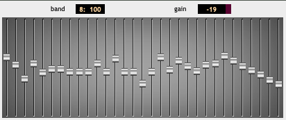
GRM Tools Equalize
Graphic EQ's have a series of vertical faders, spaced by equivalent musical interval. A good graphic EQ may have bands spaced every ⅓-octave. In their neutral central position, they neither boost nor cut frequencies, but as slid up or down, they may increase or decrease the strength of the signal spectrum that falls within their band significantly, perhaps as much as 24 dB (every 6 dB is a doubling of amplitude).
Parametric EQ's
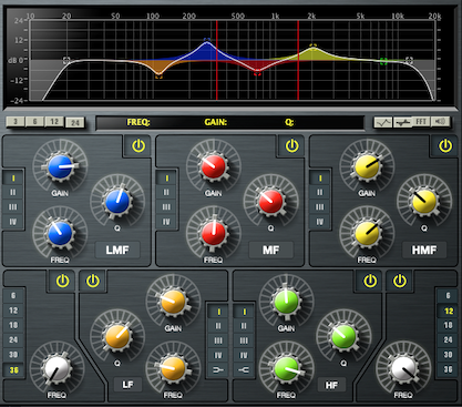
Digital Performer MW Equalizer
Parametric EQ's, such as those discussed in the Mixing Console section, will have a series of peak/notch filters, meaning they can either boost or cut frequencies inside their tuned band. The user can usually control the center frequency of the band, the width of the band (Q) or its slope, and the amount of boost or cut. A frequent mistake is sweeping the band's frequency while the boost/cut is set to zero resulting in no change to the signal. Some bands may offer a high or low shelving filter. On the low end will be a highpass filter (so a gentle slope towards a significant negative dB), and on the high end, the opposite with a lowpass filter.
EQ Audio Examples
| Dry Signal | 3K boost, HP to 2K cut | 150 Hz boost, 600 Hz cut |
130 Hz boost, LP to 440 Hz cut |
|---|---|---|---|
Compression and Limiting
Compression can be an extremely important and useful tool for an electronic composer. A compressor effect transforms the amplitude of an input signal in a non-linear fashion based on both a compression ratio, and an area called a knee, which is the amplitude at which the non-linear gain reduction begins, usually set by a threshold control. While mixer faders or DAW volume curves either add or subtract from a signal's gain linearly regardless of the input amplitude, compression most often passes lower amplitudes linearly, but gain-reduces or squashes the areas where the signal is at higher amplitudes, creating a deliberate reduction in dynamic range. A compression ratio setting determines the amount of compression above the threshold. A 5:1 compression ratio means that a a signal that is 5 dB above the threshold going in will be reduced to 1 dB above the threshold going out. Compression at higher ratios may alter the timbre of a sound, giving it a "punchier" character when applied to to sounds with sharp transients, such as kick drums or basses. Normally, compression occurs when the gain of the input signal itself rises above the knee amplitude, but more recently, compressors have included the option to have the amplitude peaks of a different signal trigger the gain reduction, and this is called side-chain compression.
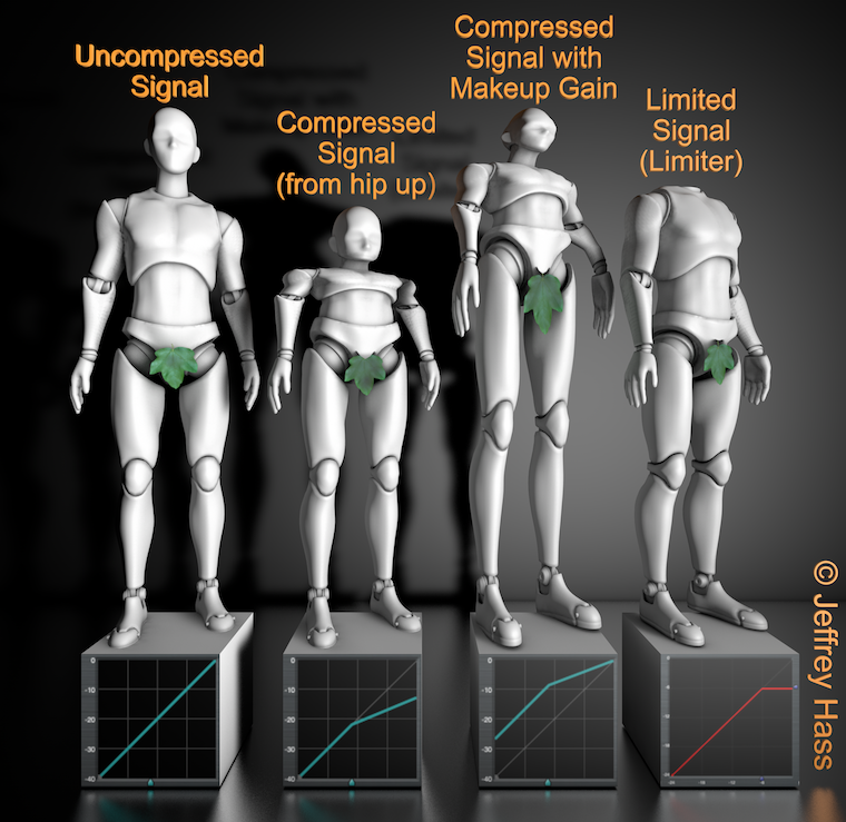
Looking at the first three male robot figures from the left above, notice the transfer function on the front of the bases. The x-axis is the amplitude of the input signal and the y-axis is the output signal, with the blue triangle on the bottom indicating the threshold or knee. With no compression, the first figure passes amplitudes linearly, that is, whatever the amplitude going in is the amplitude going out. The second figure shows that amplitudes up to around the -22 dB level are passed linearly, but above that knee they are reduced in gain. This would lead to an overall reduction of total amplitude, and that may be useful in some circumstances.
However, compression is most often used not to reduce overall amplitude, though it can be very useful in noise reduction, but to do quite the opposite. Rather than making the loud parts softer, by making use of a control called make-up gain, the compression of higher amplitudes only allows the entire signal to be boosted. The third robot above takes the compression threshold and ratio of the second robot's parameters, and, using a high level of make-up gain, boosts the entire signal. The advantage of using compression to do this is that it allows for the highest gain possible without clipping the higher amplitudes of the signal. In fact, if you looked at the waveforms of many popular hip-hop songs of earlier decades, they would look essentially like two horizontal 2 x 4's, with very little low amplitude spots. Or if you wonder why you can hear the TV commercials when you go into another room to get a snack, even though you haven't touched the volume, they also often use massive compression.
Fooling mother nature comes at a cost, however, and extreme ratio compression suddenly kicking in and out can create unwanted artifacts–a common one is called compressor heaving. Most compressors have an attack and decay setting that helps with this by easing in and easing out the compression, rather than having it suddenly reduce a sharp transient. Because these attacks may need to be triggered suddenly or miss sharp transients, better compressors also have a function called look-ahead that helps smooth this out as well as stereo linking, so the compression of one channel is also transferred to the other.
The fourth male robot in the illustration above demonstrates the action of a limiter. A limiter can be viewed as an extreme compressor, in that at its threshold it will reduce all amplitudes above that to the threshold amplitude. Using a limiter to avoid clipping may at first look seems like a great idea. However, it significantly alters the characteristic of a sound. In general, it may be better to use compression and good gain control, but a limiter has its uses as a failsafe last resort where unpredictable higher amplitudes simply need to be stopped, such as live sound reinforcement or protecting speakers. A limiter will have similar controls to that of a compressor, minus the compression ratio.
Compression Audio Examples ("Good Times!")
| Uncompressed Signal | Compressed Signal 6:1 with No Makeup Gain | Compressed Signal 6:1 with Makeup Gain |
|---|---|---|
Chorus
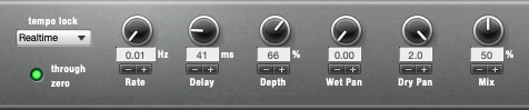
A chorus effect adds one or more "voices" to a signal by both pitch-shifting and possibly delaying the original source. It is great for thickening sounds and, as the name implies, mimicking larger ensembles from a thinner sound source. Chorusers typically have one or more low frequency oscillators that can cause the doubled pitch shifts to rise and fall above and below the source pitch as well, with the amount of shift controlled by a depth parameter. This effect is sometime also called a vocal doubler, though some parameters may be different.
Controls: lfo, depth. Detunes input signal by a certain small interval called depth (or multiple intervals), and allows that interval to be modulated by an lfo. May also include delay of chorused output.
Chorus Audio Examples
| Dry Signal | One Added Voice with Delay | Two Added Voices with Delay |
Fast LFO and Wide Depth |
|---|---|---|---|
Echo (delay, multi-tap delay)
Acoustically, an echo is the repetition of sound impulses created by mechanical reflection in an environment. Echoes in the physical world generally repeat with each subsequent repetition attenuated in amplitude, the decay rate of which is determined by the inefficiency of the reflecting material. In an environment where multiple surfaces exist, multiple echoes may form rhythmic patterns. Digital signal processing can not only reproduce the basic physical properties of echoes, but create artificial enhancements not found in nature, such as echoes that increase in amplitude over time, rhythmic patterns synchronized to other tracks, or an indefinite continuation of the echoes. Also unlikely in nature is the single, short delay echo called a slapback echo, demonstrated below.
Back in the day, a technique for creating multiple echoes used tape loops on tape recorders, feeding a signal onto a record head, and looping it back into the machine input from a playback or sync head. The tape speed determined the time delay between echoes, and the amount of attenuated signal sent back determined how long the echoes would continue. Now, however, almost every major DAW has DSP plugins called either echo, delay or multi-tap delay. Delay effects generally differ in use from reverbs in that the echo density does not build up to a single perceived late reverb entity, though many delays can mimic that. Individual echoes are refereed to as taps. Delay settings can determine the number of taps, their delay factor and their attenuation level. In addition, most delays can feedback the output echoes back into their inputs, so even a single tap echo setting can produce multiple echoes via feedback. Stereo or multichannel delays can have different delay times and levels for each channel or speaker, providing for a pingpong effect if desired. The feedback level is normally set to less than unity gain, unless the user wishes the echoes to continue indefinitely or even increase in amplitude (eventually to clip and distort if not stopped). Another parameter to pay attention to is the mix amount. If you have an inline delay in a channel strip and the delay mix is set to 100%, you will not hear the original sound, and if a single-tap delay, will not be perceived as a delay at all. This may be useful for time-aligning live audio in a sound reenforcement situation. However, if you are busing your source signal to a dedicated delay auxiliary channel, then you will want to set the delay mix to 100% to nix the source sound in that aux. As with reverb, be very careful not to inadvertently cut off the end of the delay signal, which will likely extend beyond your source file. When selecting a region to bounce, be certain it extends far enough for the delay signal to die away completely.
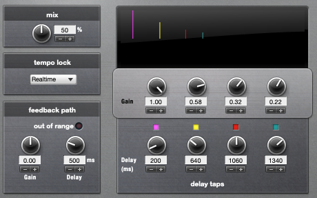
Digital Performer Echo with 4 delay taps
Echo Controls: echo time (often different for stereo locations (left, center, right)), feedback (for multiple echoes which die away or build up), pre-delay. Software multi-tap delays may allow sync'ing 'taps' to a rhythmic grid, and some may provide separate filters for each output channel.
Echo Audio Examples
| Dry Signal | 100 ms Single Slapback | Mono Multi-tap 150-300-650-900 ms |
Stereo Echo with Feedback 200 ms Left, 440 ms Right (*) |
|---|---|---|---|
Flange, phaser
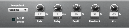
The flanging effect is created by minutely delaying (1-20 ms) a copy of the input signal and remixing with the original, creating a classic comb filtering effect. The resulting constructive and destructive interference reinforces varying sets of harmonically-related frequencies. As delay time is altered by an LFO, to a degree set by the depth control, it creates the flanger's unique sweeping effect. The effect can be enhanced by feeding back part of the flanged signal into the input again. If the fed-back signal is inverted, a slightly different reinforcing effect can be created. Called flange because it originally involved playing a second copy of a reel-to-reel tape which was then slowed down by an engineer lightly touching a reel flange to put it out of phase with the source tape. A type of flanging is called barber-pole or infinite flanging, where as the name suggests, the rising or falling harmonic emphasis seems to go on in one direction forever, similar to a Shepard tone.
Controls: rate, depth, delay, feedback, stereo image.
Flanger Audio Examples
| Dry Signal (guitar) | Mild Flange | Extreme Flange with Stereo Phasing |
|---|---|---|
Phasing or a phaser effect is very similar to flanging, except that through the use of time-delayed allpass filters, it does not emphasize primarily the harmonic partials as strongly in its sweep.
Pitch shift
Real-time pitch shift transposes the incoming audio, whether in realtime or recorded and transposes by pitch or ratio. Some effects provide the ability to mix the original with the shifted material. More sophisticated pitch shifters allow the outgoing signal to be delayed and fed back into the pitch shifter to create a cascading effect. The second example below uses GRM Tools Pitch Accumulator for that purpose, but without it, an effect send to a delay then back into the pitch shifter can be set up to accomplish the same thing. Even with the best pitch shifters, the farther away the transposed pitch gets from the original, the more artificial it is likely to sound, particularly if separate formant controls are not used in more sophisticated phase vocoding applications.
Pitch Shift Audio Examples
| Single Pitch 50% Mix | Double Pitch with Delay and Feedback (GRM Tools) |
|---|---|
Gate (reverse gate)
A gate allows signal through only after its input reaches a certain amplitude threshold. What is extremely fun with a gate is to use another signal or even MIDI data as the gating input (often called a key) to let the signal input through, as demonstrated in the audio example below. Good for sounds with low-level noise (like tape hiss, if you remember what that was), but easily leads to an artificial silence between impulses. A reverse gate with certain attack and decay settings may make an input signal sound reversed because of the way it shapes it dynamically. Some plug-ins allow for a specified, repetitive gating rhythm to be overlaid on a signal, often called a pattern gate.
Controls: threshold, attack, decay, smoothing
Gate Example
| Human Speech Gated by Dog Barks |
|---|
