Chapter Four: Synthesis

10. Phase Vocoding (PV)
Phase vocoding (pv) is a form of synthesis by analysis in that a digital sound file or stored buffer is analyzed and is then resynthesized by the phase vocoder. Unlike the similarly-named channel vocoder, due to the spectral analysis phase, pv is a purely digital technique. The classic use of a phase vocoder is to stretch the original sound out in time without changing its original pitch. Other possible uses include compressing a sound in time without changing the original pitch or changing pitch without changing original time. Often a combination of the two (alterations of both pitch and time) is used. Unlike the classic studio technique of changing the speed of an audio tape, where time change is linked to pitch change (the slower the tape, the lower the pitch and vice versa), phase vocoding was a welcome tool for composers when it came along with the advent of digitized audio files and analysis algorithms as early as 1966 (Flanagan and Golden, Bell Labs). More practical phase vocoders were developed in the 1970's and 80's, perhaps most notably Mark Dolson's in 1983. These took advantage of the much higher computational speed available at the time. Miller Puckette, creator of MAX and Pd, might be credited with developing the first real-time phase vocoder. Most recently as of this writing, a C/C++ library and SDK made by Zynaptiq called ZTX is at the top of the precision pitch/speed change game and is incorporated into many popular audio software titles such as MAX and Digital Performer. The ubiquitous modern-day auto-tune algorithms are also frequently based upon phase vocoding technology (the original "classic" AutoTune, invented and patented by Harold A. Hildebrand, did not, using a non-trigonometric process called auto-correlation (see detailed talk here)).
Analysis parameters

Windowing Functions
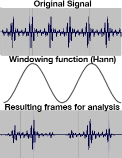
The initial phase vocoding analysis component entails a process whereby a highly granular time domain sequence of digital samples is converted into a less granular time and also frequency band representation of sound. The first part of the process involves dividing a digital sample input signal into numerous time segments or blocks of samples and then multiplying those blocks by an envelope called a windowing function, pictured without the often used overlaps on the left. The shape of these windows will have an effect on the weighting of the resultant analysis, and ultimately the character of the recreated sound. Common window shapes for phase vocoding, most being bell-shaped, are Hamming, Kaiser, Blackman and von Hann (Hanning). It is well worth the effort to try each windowing function to observe the effect on your final sound. Proper windowing, along with adding some 0's to the end of the sample frame (called zero-padding), helps minimize the phenomenon of spectral leakage, whereby the energy at a particular frequency band actually spills into adjoining bands. Click here to see diagrams of various windowing functions.
Each window is then subjected to a form of spectral analysis called an STFT, or short-time Fourier transform. Mentioned earlier in this text was Fourier's concept that all sound can be broken down into its constituent sine waves (their frequency, their amplitude and their phase relationship). While the mathematics of the STFT algorithm are beyond the scope of this article, it is important to note that the STFT procedure applies an FFT or fast Fourier transform (a math 'trick,' but highly efficient form of the discrete Fourier transform (DFT)) to the windowed samples one window at a time. A DFT analysis is considered to be discrete in time (i.e. a limited block of sample values) and discrete in the frequency domain (i.e. it can be pictured as isolated spectral lines). So for each window, time and spectrum have been frozen. An STFT can be viewed as a sequence of DFTs or as a bank of bandpass filters equally spaced from 0 Hz to the Nyquist frequency.
Several analysis parameters are set before analysis begins. The first is how many frequency bands will be analyzed (these are sometimes referred to as channels). Frequency bands are equally spaced by cycles per second, begin at 0 Hz and end at the Nyquist frequency (sampling rate/2). As our pitch is a logarithmic scale and the band spacing is linear, the bands' pitch resolution become less and less refined towards the low end of the spectrum. A single band that represents 20-40 Hz will resynthesize only one frequency to represent an entire octave!
The number of bands is always a power of two (256, 512, 1024...) — one reason the FFT is so efficient. The analysis actually creates a mirror for each positive frequency band in the negative (imaginary) range, with both having half the magnitude of the real frequency band measured. Among the several processes that take place after this computation, the phase vocoder throws away the negative frequencies and doubles the magnitude of the positive ones.
There is a computational relationship between the number of bands of analysis, the band frequency spacing, the sampling rate, and the number of samples in each window (frame size).
band frequency spacing = (sampling rate / 2) / number of positive frequency bands
window length in samples = sampling rate / band frequency spacing
number of bands = window length in samples / 2
The chart below demonstrates these relationships.
| bands | window length in samples |
band frequency spacing |
sampling rate |
|---|---|---|---|
| 256 | 512 | 86.13 | 44100 |
| 512 | 1024 | 43.07 | 44100 |
| 1024 | 2048 | 21.53 | 44100 |
| 2048 | 4096 | 10.76 | 44100 |
| 4096 | 8192 | 5.39 | 44100 |
The output of a single FFT of windowed samples is called a frame. It consists of two sets of values: the magnitudes (or amplitudes) of all the frequency bands, and the initial phases of all the frequency bands. For each band, therefore, its amplitude at the time of analysis can be quantified, and its phase difference from the previous frame, which gives clues as to where in that band's range the pitch may actually lie, is determined. The amplitude/phase difference pair of data for each band is called a bin. These amplitude/phase data pairs for each bin are output as x, y coordinates. The analysis portion of phase vocoding creates a file of sequential frames, each one of which holds multiple bins. The video below demonstrates what the first several bands would look like as sequential frames (with an imaginary band spacing of 20 Hz for ease of display).
PV Frame Sequence Video
Looking at the exponentially increasing frequency resolution in the table above, as represented by the band frequency spacing column, it seems like the best course of action for a really great analysis is to go with the largest number of bands possible. Not so fast! Look at the window lengths above as well—with each increase in frequency resolution comes a longer window of analysis. Time is stopped for each window — the FFT assumes all frequencies in a window occur at once, therefore, any change in frequency within the duration of the window will be missed. To get as much resolution as 1 Hz band spacing, the window length necessary would take 44,100 samples — at 44.1 kHz sampling rate, that's 1 second for each window! On the other hand, if one wished for 1 ms time resolution (that would be about 44 samples per window), it would be necessary to drop the frequency resolution down to a band spacing of 22 bands, or about 1000 Hz apart. Obviously, some compromise in the middle makes sense, due to this fundamental trade-off between time (duration) and frequency. One aspect of working with phase vocoding is constant testing of different settings to see which works best for a particular sound.
Another parameter that is set before analysis begins is the hop size. This is a measurement of how far into the input file (measured in samples) the next window of analysis will begin. Another way of looking at this is referred to as the overlap factor. Overlap is a measure of the maximum # of analysis windows covering each other at a given point. If the hop size is set at half the window size, the overlap factor would be two. Some samples would be included in two successive analysis windows as illustrated below. A higher overlap factor is great for future time-dilation. However, having a high overlap factor will cause a "smearing" effect, though many composers find this desirable.
frame size = 8 hop size = 4 overlap factor = 2

In summary then, the analysis portion of phase vocoding creates a file of sequential frames, each one of which holds multiple bins. PV analyses of long files with large numbers of bands and high overlap factors can be huge.
Resynthesis
The function of phase vocoding is not just to provide analysis data, but to use that analysis data to resynthesize the sound that was analyzed using a process called an inverse STFT. The frames of the PV analysis may be resynthesized by several methods, including the overlap-add method or the oscillator bank resynthesis method (with each method doing quite a bit of manipulation to get a smooth result). In reality, not all frames are necessarily used, perhaps every fourth frame in many situations. A sine wave is produced for each analysis band at the amplitudes specified in the pv frame. If there was no energy recorded for a band in a particular frame, then there will be no energy given to that band's sine frequency. As mentioned above, the phase data is used to resynthesis the proper pitch for each band by creating a running record of phase differences from frame to frame in a process called phase unwrapping (with fun-sounding conversions like Cartesian to polar x, y coordinates for amplitude and phase, using, for example, the cartopol object in MAX). If the frames were played out of order, the sequential phase difference data would be useless and many bands would produce the wrong frequencies.
Resynthesis is the stage at which modifications of the original sound can take place. To alter the speed of the original input signal (i.e. to slow it down or to speed it up), the rate at which frames are resynthesized can be sped up or slowed down from the rate of original acquisition accordingly. The PV interpolates between the frames to make that a smoother process, and this is where a greater overlap factor can help. Because the frequency content of each frame is not changed, changes in the speed do not result in changes in pitch. In fact, a single frame can be resynthesized to "freeze" that timbral moment in time for as long a duration as the composer wishes.
Conversely, frames can be played back at the rate in which they were analyzed, but the frequencies of the entire spectrum can be shifted up or down proportionally, resulting in change in pitch, but not one of speed. Or both speed and pitch can be altered simultaneously. A common variant is to use an additional analysis of the spectral peaks (formants) of each frame and shift them independently of the overall pitch to create a timbre shift. This is available in MOTU Digital Performer's Spectral Effects module whereby all three parameters may be changed simultaneously. Another variant would be to multiply the spacing between the bands (rather than subtracting or adding), resulting in interesting distortions of timbres, as harmonics would then have a very different, likely inharmonic, spacing.
Resynthesis can often create artifacts or anomalies in the interpolation process. Many composers enjoy using these artifacts, but many who have used phase vocoding for a long time have grown weary of hearing them become the major focus of the music. Changing analysis parameters can often avoid artifacts or make more interesting ones. Additionally, some frequencies wander between bands and can cause unnatural results. Try wider bands or use another method called MQ Analysis that tracks 'threads' within certain percentages of drifting frequency (provided by a free program called SPEAR). Pitch-tracking phase vocoding is another option. Here the phase vocoder tries to line up its bands as harmonics of a perceived fundamental frequency.
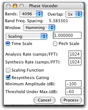
Choices, choices: Observing the SoundHack Phase Vocoder window below, you will see settings for # of bands, overlap factor, window function, time scaling (longer or shorter), pitch scaling. By selecting the Scaling Function check-box, you may draw your own variable time-stretching function or pitch changing function. Again, it is almost impossible to predict exactly how each sound will react to a particular setting, so experimentation by changing # of bands, overlap factor, window function and of course setting the time or pitch scaling you want is essential. SoundHack is/was freeware for the Mac (non-functional at this writing for current Mac OS) that every composer should have.

The simple phase vocoding examples below demonstrate a few of the common treatments for this technique using the same input file. |
|
|---|---|
| Parameter Description | Audio Example |
| Input file, no speed change, no transposition | |
| Transposed up one octave, no speed change | |
| Transposed down one octave and sped up 50% | |
| Only the first 'B' time-stretched by 200% | |
| Formants only shifted down one octave | |
References: Roads, Curtis: The Computer Music Tutorial (has a great separate appendix on FFT math), Dodge, Charles and Jerse, Thomas: Computer Music