Chapter Four: Synthesis
4. Analog Synthesis Concepts
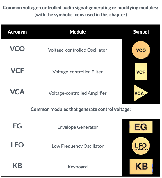
The Modular Voltage-Controlled Synthesizer
As the name implies, sounds are created synthetically via electronic circuits, as opposed to originating from sampled, or real-world recordings. In studios pre-dating integrated modular instruments, a signal path may have run through many different separate prototypical devices. With the advent of a single modular design, perhaps most famously typified by the Columbia-Princeton RCA Mark II and then the Moog modulars, all the various elements required for sound synthesis, both its generation and control, were housed in a single instrument. Some modules produced sound, some modified that sound, and others provided electrical current to modify all the others while not producing or shaping the sound signal themselves. These instruments came to be known as voltage-controlled synthesizers, with voltage being the source of both the audio and control signals.
The 1964 Moog Modular synthesizer set the gold standard for voltage-controlled synthesis in a single instrument design, and most software synthesizers (such as Native Instruments Absynth), and even synthesis programming languages these days still follow the basic architecture of that instrument. Genius designer/inventor Robert Moog's instrument was highly configurable via patching. Modules were connected via patch cords, and the total configured design was eventually referred to as a patch. It was not unusual to have dozens of patch cords routing audio and control signals to create a single sound. Subsequent lower-tier Moog models, such as the MiniMoog hardwired some of the more common connections and were not as configurable.
Voltage is used to control virtually all functions of the instrument, including pitch, timbre, amplitude over time, vibrato, and tremolo. It is useful enough to understand synthesis by simply viewing voltage as a force—the more voltage, the greater the force of change to whatever parameter it is applied. Instruments began to use a safe, non-shocking amount of voltage, normally ranging from −5 to +5 volts. For a more in-depth understanding of voltage, please see the electricity primer appendix page.
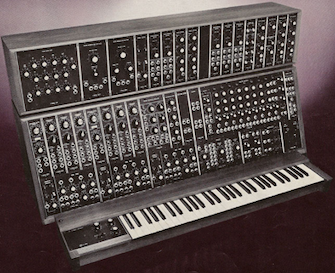
Pictured: Moog Model 55 (1974), a model once owned by Indiana University (a sad story…it was Serial #5, built in his garage…)
While many of the control connections are often not as flexible in some software programs, you can still create your own instrument designs (still called patches!) with graphic synthesis programs such as MAX, which is infinitely configurable via drawn patch cords between graphic objects which themselves are the equivalent of hardware modules (MAX, which has a free time-limited demo available, and actually comes with a set of analog-style synthesis modules called BEAP—Berklee Electro-Acoustic Pedagogy). You can follow along with these lessons if you have access to MAX. An alternative would be to download a free Eurorack synth emulator from VCV Rack.
Subtractive Synthesis
Most voltage-controlled synthesizers are modeled around subtractive synthesis techniques, where the signal path begins with a waveform (or digital wavetable that stores these functions as individual samples these days) rich in partials. These frequencies are then partially removed (subtracted), or otherwise shaped, by a filter. The antithesis of subtractive synthesis is additive synthesis, where sound is produced by summing numerous sine waves together to create composite timbres, and with no filtering.