Chapter Four: Synthesis

9. Audio-rate Amplitude Modulation(AM) and Ring Modulation (RM)
Two additional wide-spread techniques for audio-rate modulation are amplitude modulation (AM) and the related ring modulation (RM) or balanced modulation. Rather than varying the center frequency of a carrier oscillator, amplitude and ring modulation cause deviations in the amplitude of a signal after it leaves the a VCO, VCF or even after the input of real-world sound as it passes through a VCA amplifier module. As before with sub-audio rate vibrato and tremolo (see 7. Patches: Sub-audio Rate Modulation and 8. Principles of Audio-rate FM Synthesis), the module affecting the deviation of the carrier signal (in this case, its amplitude) is still called the modulator. Because the modulation will be at audio-rate, rather than using an LFO as a modulator, another VCO capable of audio-rate c.v. or a noise source (or a second real-world sound) is required, otherwise the patch is identical to the tremolo patch we saw earlier. In its simplest form, AM and RM are simply multiplying their amplitudes by each other. The spectrum of the modulating waveform, noise or audio signal combined with the spectrum of the carrier signal will determine what the ultimate spectrum of the output will be, as the formula below will demonstrate.
Looking at the AM patch below, it is this author's preference that an additional VCA be used in the patch path for two reasons: 1) the frequency-rich output of the AM can be filtered if desired, and 2) if only the final VCA were modulated and summed with an envelope generator, at most indexes of modulation (discussed below), it would be impossible to completely stop the sound via the VCA envelope–on a positive slope of the modulator, a pulse of sound would likely audibly pop out, even after the envelope completes its release.
One important distinction between AM and RM is that audio-rate AM is traditionally done with a unipolar modulating signal, while Ring Mod traditionally uses a bipolar modulating signal. If a unipolar modulating source is not available, the incoming modulating signal can be first attenuated at the VCA being modulated then, using the initial gain offset, set above 0.
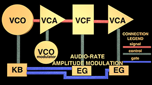
Audio-rate Amplitude Modulation Patch (click on synth to enlarge)

What we hear with AM
Sidebands: Audio-rate AM will create additional frequencies around the carrier frequency, also called sidebands. The timbral result of audio-rate amplitude modulation is much simpler than FM. For carrier frequency Cƒ and modulator frequency Mƒ as sine waves, we always hear the carrier Cƒ, and additionally the sum and difference C + M and Cƒ − Mƒ, so Cƒ, Cƒ + Mƒ, and Cƒ − Mƒ. Unlike audio-rate FM reflected sidebands (or ring mod below), if the Cƒ − Mƒ sideband is below 0 Hz, it simply disappears, according to Allen Strange.
Below are two examples with sine waves only, the first with harmonic sidebands, the second with inharmonic sidebands.
| carrier ƒ (C) | modulator ƒ (M) | result |
|---|---|---|
| 400 | 100 | 300 (Cƒ −Mƒ), 400 (C), 500 (Cƒ + Mƒ) |
| 400 | 278 | 122 (Cƒ −Mƒ), 400 (Cƒ), 678 (Cƒ + Mƒ) |
For richer waveforms, or amplitude-modulating real-world audio, not only will we hear all frequency components of the carrier and modulator signals, but we will hear ALL sums and differences between ALL of the components in the audio range, creating a more complex sound. Additionally, by over-modulating the amplitude of the carrier, even with two sine waves, additional frequencies will be created through waveform distortion and the resulting sum and differences.
Strength of sidebands: As with FM, the strength of the sidebands also contribute to the overall timbre of the output. Very simply, with AM, the stronger the modulating waveform permitted into the amplifier (via the amplifier's attenuator or other gain control of the modulating signal), the stronger the sidebands, though they will never exceed half the strength of the carrier. As with FM, the total amplitude gain above OR below an otherwise unmodulated signal passing through the amplifier is called its peak deviation. It is most common to offset the amplifier so some sound is passed when no modulation is occurring (with a totally attenuated modulator), otherwise the sound stops.
The formula for the modulation index I of AM is: I = peak amplitude deviation/carrier amplitude
If the maximum signal amplitude is a conceptual value of 1.0, the maximum modulation with a symmetrical waveform before distortion will be amplitudes between 0 and 1, with the unmodulated carrier at 0.5 and a peak deviation above or below the carrier amplitude as 0.5. Any stronger modulation will distort the carrier signal and cause additional sidebands. So the maximum modulation index (in our conceptual case of 0.5 peak amp/0.5 carrier amp) before distortion is I = 1.
AM Synthesis Controls:
Waveform of the modulator controls shape of amplitude deviation. The frequency spectrum of the modulating wave combines with the frequency spectrum of the carrier signal passing through the VCA, outputting the spectrum of the carrier and the sum and difference between all their frequency components.
Depth of modulation is normally controlled by the attenuator at the c.v. control input of the module being modulated. The more of the modulating signal allowed into the module, the greater the deviation (or effect) of the parameter being modulated. On many modern synths, the depth of modulation is controlled by the mod wheel—what sort of modulation is determined by the synth’s patch.
Rate: The frequency of the modulator determines the rate of modulation. Above 20 Hz for most forms of modulation, stranger things, such as additional frequencies begin to sound.
Exponential or Linear Control Input VCA c.v. control inputs are often labeled linear or exponential (or there may be a switch selecting one response or the other). On a VCA, linear response to c.v. changes means the output signal voltage will linearly mirror the input voltage based on the attenuator setting. An exponential response means the VCA will respond exponentially in proportion to the attenuator setting. For classic AM, a linear response is best.
Two-quadrant vs. Four-quadrant: Without getting too far into the weeds, if your VCA has this choice (as does the MAX BEAP VCA), here is what it means. Two-quadrant, when the offset property will not go below 0 gain into "negative" territory and remains unipolar. This is the typical setting for straight AM. However, for ring and balanced modulation, where the carrier and modulator frequency will be removed from the spectrum, the method used by such modules are four-quadrant response, creating "negative gain" and resulting phase cancellation of these frequencies.
Double modulation: Double AM modulation is possible, whereby an already AM-modulated signal is passed through a second modulated amplifier, creating a richer frequency spectrum. If carefully tuned, it can be used to bring out specific frequencies through doubling in relation to other non-doubled sidebands.
What we hear with Ring Modulation (aka Balanced Modulation):
Ring modulator modules were incredibly popular at the inception of the modular synthesizer and are still found today in software and hardware synthesis. Additionally, stand-alone (usually home-made) ring modulator circuit boxes, invented in the 1930's for telephony, and being fairly simple circuits, became very popular and were used by a large number of composers beginning in the 1950's to modulate real-world audio signals along with electronic signals.
One might think (as I once did) they are called "ring" because they can very easily producing "ringing" inharmonic bell-like sounds. However, the name apparently comes from the circuit diagram where the key components (usually diodes), form a clockwise or counterclockwise circle or ring. Composers such as Karlheinz Stockhausen used the ring modulator extensively in his electronic works, perhaps most famously in his two-piano work Mantra (1970), whereby both mic'ed pianos were passed through the same ring modulator signal input and interacted with a variably-tuned sine wave generator.
As mentioned above, ring modulators use two signal inputs (which could be called carrier (C) and modulator (M), but they interact act more or less equally) These are normally plugged into a Ring Modulator module that may have attenuators for one or both signals (as our synth above does), and a single signal output. The signals can both be electronic, both be real-world audio, or one of each. The output of the module is simply the sum and difference between all frequency components of the two inputs without the original input frequency components, which are canceled out in the process (via the four-quadrant method and the circuit design). So, for sine components:
Ring Modulation = Cƒ − Mƒ and Cƒ + Mƒ
A significant difference from simple amplitude modulation is that if Cƒ − Mƒ produces a negative sideband, it is reflected back from 0 Hz just as in FM synthesis, whereas in AM it just disappears. In addition, Curtis Roads mentions key difference between digital RM, which is a simple multiplication of the two signals, whereas in analog RM, the various circuits may have their own timbral flavor, often adding additional odd harmonics caused by the clipping of the analog diodes.
If the two sounds are in a harmonic relationship, some of the original components may be recreated, even fortified by the sum and difference results. If the inputs are in an inharmonic relationship, rich spectral structures can be created. In both cases, one or both input frequencies can be above the audio range, leaving only the lower sidebands to be heard.
Technique suggestions:
One very popular technique with both AM and RM is to vary the pitch of only one input signal, while leaving the other static (in AM, this would usually be the modulator). With each new carrier input note, a new spectrum is created by the sum and differences with the fixed frequency. The example below uses a triangle wave carrier VCO and a sine wave modulating VCO fed into a ring modulator. The carrier quickly changes frequencies (using sample and hold), while the modulator produces a steady pitch...therefore, each carrier pitch change creates a different combination of sidebands.
| Ring Modulation Example | |
|---|---|
This is a demo paragraph and hidden. | This is a demo paragraph and hidden. |
PLAY ALONG: If you haven't yet downloaded the free VCV Rack app, click here for information. This example requires the installation of the free BOGAUDIO modules before opening. Open Rack and click on Library→Manage Plugins and navigate to BOGAUDIO library, then install.
Download the VCV Rack RING MODULATION example. Once downloaded, fire up VCV Rack and use the File-Open menu command to open it, or you may get an error message if you double-click on the file itself.
