Chapter Four: Synthesis
6. Patches: The Basic Patch
The basic patch, as its name implies, allows for control of three essential aspects of sound utilizing the three main signal path modules: frequency (VCO), timbre (VCF) and amplitude (VCA). The VCO initiates the sound wave and controls its frequency. It also determines the initial timbre, which is determined by the waveform option selected. The VCF filter module shapes the timbre via the filter type chosen, the initial c.o.f. (see cutoff frequency), the amount of Q, and the movement of the c.o.f. over time as controlled by an envelope generator. The amplitude of the sound (its beginning, change over time, and end) is shaped by the VCA.
The primary functions of these main modules are controlled, via control voltage, as follows.
- A keyboard outputting 1 V/oct controls the frequency of the VCO.
- An envelope generator (ADSR) patched to the VCF c.o.f. input controls the movement of the filter c.o.f. during the course of the note.
- A second envelope generator (ADSR) attached to the gain control input of a VCA controls the dynamic shape of the note over time, including its start and end.
- The keyboard gate output (separate from its 1 V/oct frequency c.v.) connected to the envelope generators also GATES the EG's to begin their c.v. stream when a key is depressed and to move to their release phase when a key is released.
PLAY ALONG: As of this writing in 2024, a free working virtual Eurorack modular synthesizer simulation is available for download called VCV Rack 2 (it installs as the RACK app). In addition to the basic free modules, there is an available library of thousands of free and paid additional modules. The following pages will provide a downloadable example of patches discussed at the bottom of each page, with a free downloadable library addition needed for the Sample and Hold and Ring Mod patches.
To download VCV Rack 2, go to vcvrack.com and follow the install directions.
The Basic Patch
click on synth for enlarged image in a new window
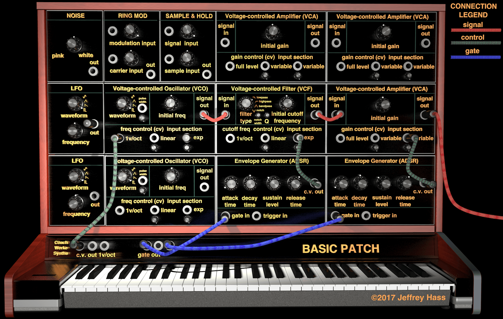
Basic Patch Breakdown
Connections:
Signal Path (red cables): VCO signal output→VCF signal input; VCF signal output→VCA signal input; VCA signal output→to board/amp/speakers.
Control Path (green cables): KB c.v. output→KB c.v. input (usually 1V/oct); Envelope Generator(EG)1→filter cutoff frequency c.v. input; EG2→amplifier gain c.v. input.
Gate Path (blue cables): KB gate output to both EG's.
Controls:
VCO adjustments: waveform choice (sine, triangle, etc.), initial frequency offset pot to tune VCO to KB (i.e. middle C can be whatever pitch you want, all other pitches adjusted accordingly). If KB is connected to EXP c.v. input with attenuating pot, the pot can be adjusted to produce microtonal increments rather than 12TET intervals. If pulse wave is selected waveform, then pulse width can be controlled both by an offset and c.v. applied to pulse width input.
VCF adjustments: filter type choice (LP, HP, BP, notch), initial cutoff frequency (what frequency the cutoff ƒ ( or center ƒ for BP and notch filters) starts at before c.v. is applied), Q or resonance, c.v input connected to either 1 V/oct input (in which case c.o.f. will sweep 5 octaves for a 0-5 V EG output, or sweep as far as 10 octaves if a bipolar LFO or VCO waveform is applied for filter modulation), or attenuated linear or exponential c.v. input, in which case the attenuator pot will cut down on how far the c.o.f. is swept. If a notch filter is chose, the notch width may be adjustable with a pot and/or a c.v. input.
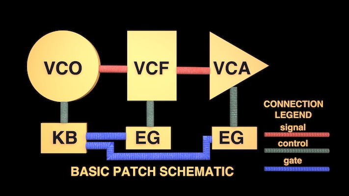
Know your patch cord functions
In designing patches, from the simplest to the most complex, it is extremely helpful to mentally separate all the connections into path categories, as shown in the schematic above.
- Signal path connections, pictured in red, convey the audio-rate signals we eventually hear.
- Control path connections, pictured in green, convey the control signals that affect the function of modules. While we may hear their affect on the sound, we don't actually hear the control signals themselves. In the basic patch above the keyboard voltage controls the frequency of the oscillator, one EG controls the movement of the c.o.f. of the filter, and the other EG controls the amplitude of the sound.
- Gate paths emanating from the keyboard gate outputs, pictured in blue, control the EG timings i.e. when they start their attack phase (key down), and how long they hold their sustain level while the gate signal is at a non-zero voltage before beginning their release phase when the gate signal returns to 0 V (key up).
Download the VCV Rack Basic Patch example. Once downloaded, fire up VCV Rack and use the File-Open menu command to open it, or you may get an error message if you double-click on the file itself.
