Chapter Four: Synthesis
6. Patches: The Basic Patch | Page 2
Meet the Signal Path Modules
Every synthesizer or softsynth will have its own unique module design, but most have at least certain basic features in common, which we try to capture below.
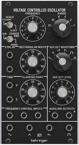
The Voltage-controlled Oscillator (VCO) outputs a continuous stream of alternating current (AC) voltage which may be used as either a signal or control source (or both). The overall shape of the stream may be selected by a waveform selector, or in the case of many early modular synths, multiple waveforms are produced simultaneously and output through separate jacks. In addition, for the pulse waveform, an initial pulse width control is often provided, along with a control input and attenuator for further pulse width modulation, included in the pictured module here. The amplitude of the VCO output is normally fixed at the maximum reference for the instrument (a swing from -5 to +5 volts, for example), with no possibility for amplitude control at this stage. Pictured left is a Behringer Eurorack replica of the legendary Moog 921 oscillator (hover to see image of original), which was one of the more complex oscillators made.
The oscillator's initial frequency offset (the frequency before control voltage is applied) is set for either a wide sweep (±6 octaves), or a much narrower one-octave range, interestingly centered on organ-stop feet-designated octaves via the right knob. This gave the user the choice of a far less precise but huge tessitura, or a more precise fine frequency control. These oscillators were tuned either by ear, or a frequency counter if you were lucky enough to own one, and they often drifted as the electronics warmed up. Some oscillators had a coarse and fine tuning knob. And many, like the Moog, also had a subaudio option, though instruments with LFO's might not.
The Moog 921 did NOT have separate 1 V/oct, linear and exponential frequency control c.v. inputs like many (because the Moog c.v. concept conditioned the c.v. before the module c.v. inputs). But it did have a clamping point control that would offset the phase of it's waveform to a specific phase angle upon a trigger. This might be great when used as a subaudio control signal, to say have a vibrato start at the same point with each note. Or it would act as a sync to force in-phaseness with another oscillator. Sync is still used, even on Eurorack synths and creates some very interesting timbral effects. Finally, the Moog had a separate Aux output at the same frequency as the main waveform, but its waveshape and level could be controlled.
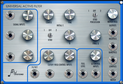
The Voltage-controlled Filters (VCF) might be either a single type, such as a lowpass, or, as is the case with this Emu (Eµ) Modular System Universal Active Filter, provide multiple filter types in one module. This filter can accept and mix three separate inputs, and output four separate filter types simultaneously. The initial cutoff frequency offset has a coarse and fine tuning. The highpass and lowpass rolloff at 12 db/oct and the bandpass 6 dB/oct to either side of the center frequency. The notch has a straight -40 dB notch cutoff modified around the cutoff frequency (c.o.f.) by the notch frequency pot.
The filter Q amount is initially set by the Q control knob, and can be multiplied by exponentially-factored control voltage (each additional volt adds a factor of 2), from .5 to a whopping 512, which can cause as much as 54 dB gain. Both the Q control voltage inputs and the cutoff frequency c.v. inputs have full-level and attenuated jacks.
The Keyboard Percussion switch routes a trigger and gate from the keyboard to the Q circuit which causes it to ring when triggered and then decay with the Final Q length set via a knob when released.
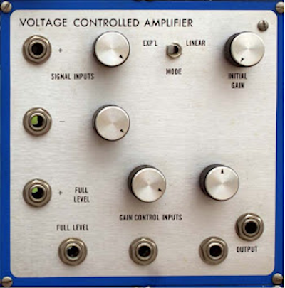
The Voltage-controlled Amplifier (VCA) was the necessary element at the end of the signal path to control the overall dynamic shape of a note or sound event. In this case, the initial gain offset would be set below the level of audibility, so when an envelope generator went to 0 volts, the sound would not be heard. In this sense, a VCA is more of an attenuator than an amplifier, since the maximum signal level for many VCA's is unity gain. Additional VCA's can also be used in the middle of a patch for things like controlling the FM modulation index or for amplitude modulation, as will be covered in the following section. In those cases, the initial gain may be set to not completely cut off the signal at 0 volts c.v..
The Emu Modular System amplifier pictured has fairly simple features. It accepts up to three signals, one in inverted phase, and three control voltage inputs, with two capable of being attenuated. With multiple signals, the amplifier can supply a maximum gain of a factor of two (or 6 dB). Additionally, the mode switch allows for the amplifier to respond to c.v. linearly or exponentially. For a natural envelope the way we hear, exponential is a good choice, since the EG's c.v. slopes on older instruments are linear.
More modern VCA's (particularly digital VCA emulators) may offer a choice between two-quadrant and four-quadrant operation via a switch, or toggle. In two-quadrant mode, the VCA will remain inactive if the control voltage descends into the negative domain. This is a standard mode for a final amplifier in the signal path. In four-quadrant mode, the amplifier will increase gain equally for both positive and negative c.v., but will invert the output for negative c.v.. This is the mode one would choose for amplitude modulation and in particular, ring-style modulation (if a ring modulator wasn't used) when using a bipolar control signal.
