Chapter Four: Synthesis
3. Filters
Filters are normally used to remove specific frequency components from a complex sound, hence the technique is often called subtractive synthesis, mentioned previously . This is not an entirely accurate description, since filters may also add energy to portions of the spectrum. Most analog synthesizers of the '70's and '80's came with the following four basic filter types (they are carried forward today on digital instruments with many variations):
Lowpass, Highpass, Bandpass and Notch (sometimes called Band Reject).
Lowpass Filter
Lowpass filters cut off high frequencies, pass low frequencies
Highpass Filter
Highpass filters cut off low frequencies and pass high frequencies
Bandpass Filter
Bandpass filters pass a certain band of frequencies and roll off frequencies on either side of the band
Notch Filter
Notch (band reject) filters cut out a notch or band in the center and pass frequencies to either side of the notch
Looking at the graphs above, notice that most filters do not suddenly cut off sound at a specific frequency. Rather, they "roll off" the frequencies gradually, for example by a reduction of 12 dB's per octave, determined by the sharpness of the filter, or steepness of the filter rolloff. The filter's cutoff frequency (c.o.f.) is the point a specific frequency component would have lost approximately half the power (−3 dB or .707 RMS) of unaffected frequencies, often referred to as the half-power point. Bandpass and notch filters have both an upper and lower cutoff frequency. A common synthesis technique is to sweep the cutoff frequency up or down to provide a spectral shape to a sound over time (this is what each video example above does). In classic synthesis techniques, cutoff frequencies are usually controlled by an envelope generator or an oscillator (timbre modulation). The portion of the sound not reduced by 3 dB power or more is called the passband, while the rolled-off portion from −3 dB down to −∞ is called the stopband.
ADDITIONAL FILTER TYPES
In time, additional filter types became available, some in analog form, but most in digital form due to the complex calculations required. These include:
Low Shelf and High Shelf
A low shelf will either cut or boost signals below a c.o.f. in a manner resembling a shelf, or an equal strength amplitude band past the rolloff.
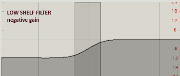
Low Shelf Negative Gain
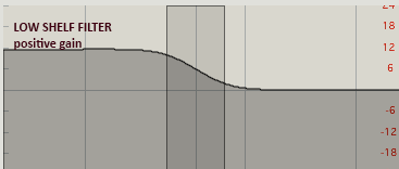
Low Shelf Positive Gain
A high shelf filter will either cut or boost signals above a c.o.f. similarly.
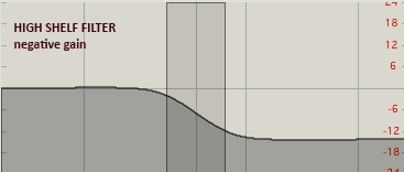
High Shelf Negative Gain
High Shelf Positive Gain
Peak/Notch Filters
Peak/notch filters boost or cut spectral components within their band without affecting the surrounding frequencies outside of it. Controls are similar to the bandpass and notch filters shown above, with the degree of boost or cut and the width of the peak or notch also controllable with the 'Q' setting (sometimes labeled as bandwidth (BW)), examined on the next page. A positive or negative gain value determines whether it is a peak or notch or flat in a single control. With the filter gain parameter set to a negative value creating a notch, there is no difference between this filter and the classic notch filter above. However, by dynamically changing the gain over time, the peak/notch filter has the ability to change to a peaking filter, while a straight notch filter above does not have that capability.
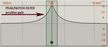
Peak-Notch Positive
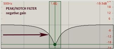
Peak-Notch Negative
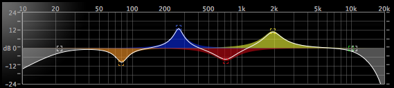
Peak/notch filters are frequently used for the mid-band frequency controls of multi-band equalizers where they are connected in series (see next page). Pictured below is MOTU Digital Performer's Masterwork EQ. On the low end and high end, pictured in gray, are the highpass and lowpass filters we saw above, but the four mid-bands, pictured in colors, are peak/notch filters with alternating cut and boost.
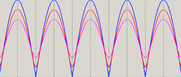
Comb Filter
A comb filter creates a series of evenly spaced bands (or notches) that resemble the 'teeth' of a comb when excited by a resonant frequency. The teeth are created by constructive and destructive interference. A group of comb filters is often used in parallel to resonate multiple frequencies of a signal. A short delay with feedback can create a comb filter. Acoustically, we may experience a comb effect if the same signal arrives at our ears at a slightly different time. Similarly, placing a second microphone at certain different distances from a source can also create an unwanted comb effect.
Comb Filter
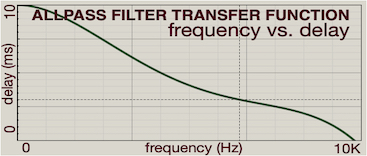
Allpass Filter
Allpass Filter
An allpass filter may sound like a contradiction in nomenclature, in that it passes all frequencies at equal amplitude, and therefore does not seem to filter in the traditional sense of frequency boost or cut. What it actually does is change the phase of various frequencies via time delay, as shown in the transfer function graph above. The output sound may be colored, particularly when played against the input signal, because normally lower frequencies are time-delayed more than high frequencies, a characteristic referred to as dispersion. The coloration is particularly noticeable in non-steady-state transient attacks or decays. In digital or electronic circuits, these may be used to "fix" certain phase displacements, but for our purposes, parallel banks of allpass filters plus comb filters are often used to create reverb effects and other constructive/destructive interference techniques that require both time and frequency alteration.
