Chapter Four: Synthesis
3. Filters | Page 2
What is filter Q?
Many filters come with a control called Q or resonance (sometime called feedback, emphasis, quality or regeneration), which feeds a portion of the filter's output back into its input. In the case of a lowpass filter, increasing the Q would cause any frequencies present near the cutoff frequency to be emphasized. This makes sweeping the filter even more apparent. The lowpass filter on the left has a Q near 1, with no emphasis around the cutoff frequency. The lowpass filter on the right has a Q of 5, where you can see the frequencies around the c.o.f. are being emphasized beyond their original gain. Similar emphasis occurs around the c.o.f. with highpass filters. Play both the examples below to hear the difference Q values make.
Lowpass Filter Q = 1
Lowpass Filter Q = 5
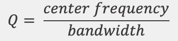
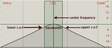
For a bandpass filter, Q is inversely proportional to bandwidth and can be calculated using the formula where both center frequency and bandwidth are in Hz:
A high value for 'Q' denotes a narrow bandwidth filter, and a low value denotes a much broader bandwidth. As one sweeps a filter center frequency higher, the bandwidth needs to widen to maintain the same value of Q. As the band narrows, energy previously spread out over a broader range is concentrated on a smaller range of frequencies and can be very intense when a strong component of the input signal is centered on the passband. Too much 'Q' can cause a howling noise or excessive feedback, particularly when energetic frequency components fall within the passband.
Use the calculators below to explore the relationship between center frequency, bandwidth and Q.
Q Calculator
Enter the center frequency and bandwidth in Hz:
Bandwidth Calculator
Enter the center frequency in Hz and value for Q:
Combining Multiple Filters in Parallel or Series plus Formants
Filters can be combined in various ways for various purposes. Filters can be connected in a series or cascade, so that the output of one is fed into the next. This arrangement steepens the rolloff and narrows the passband if the center frequencies are identical. With series connections, it is important that some frequency components be passed from the first to subsequent filters for treatment, as is the case with the series or EQ peak/notch filters discussed on the previous page.
 demonstrated here→
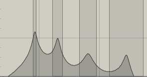
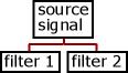
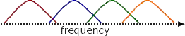
Filters can be connected in parallel so the a single source is fed independently into several filters whose outputs are then summed. This arrangement is ideal for creating multiple areas of resonance called formants, discussed earlier.
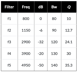
For example, a complex sound source can be shaped to sound like a soprano's vowel 'A' with multiple bandpass filters. Their center frequencies (Hz), relative amplitude (dB) and bandwidth (Bw in Hz) would be:
For a full list of American vocal-type (soprano, alto, etc.) formants from the Csound manual, click here.
Filter Poles and Zeros
Areas of resonance are referred to as poles whereas areas of non-resonance are referred to as zeros. A four-pole filter, therefore, might consist of four bandpass filters connected in parallel as pictured.
Synthesis Filter Control
Controllable parameters for synthesizer filters usually include:
- the filter type (lowpass, bandpass, etc.)
- the initial frequency: where the cutoff frequency starts before any controls are added to it
- the attenuator: how far the cutoff frequency will be swept by the control signal
- the amount of Q or resonance
The most common mistake in using filters in a synth patch is an attempt to filter frequencies that are not present in the source signal. When learning how to use filters, use a spectrally rich signal like noise or a complex waveform (i.e. not a sine wave). The second most common mistake is to have the cutoff frequency set so low (for a lowpass) that all the signal is attenuated (no sound) or so high that no frequencies are affected (no filtering).
Most illustrations on this page were made from Cycling74's MAX software using the filtergraph~ object.