Chapter Two: Studio Gear
4. Mixing Consoles | Page 2
Input Channel Strips
A mixing board will consist of a number of input channels controlled by identical channel strips (narrow vertical arrangements of controls). If you learn how one strip works, you've learned how they all work, at least for that board. The layout and minor differences in functions vary between manufacturers and models, but they all have the same basic elements.
Below, we will view sections of an input channel and their function one or two at a time.
Channel Strip Inputs
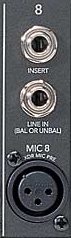
Inputs to a board, patched into the back or top, consist of line level inputs, from devices such as synthesizers and computer audio interfaces (usually balanced ¼"-TRS, but accepting unbalanced ¼"-TR ); microphones (almost always XLR), for which there is often a separate preamp section; and possibly tape inputs, for ancient devices such as reel-to-reel tape recorders and CD players (usually RCA). Unless you buy a vintage board, chances are the channel tape inputs will be gone and replaced by one or two dedicated STEREO, TAPE or 2TR IN channels (2-track input, such as a CD player or an iPhone audio cable). In addition, one might be able to route digital input signals sources (such as ADAT, AES/EBU, etc.) to the channel strip on digital boards using the board's internal I/O setup. Many boards now also feature several stereo channel strips, where there are Left/Right inputs with one set of controls for both channels.
Some boards also include a single channel insert input, or a direct in and direct out. The single channel insert, which is usually a TRS jack, allows for an effects loop input and output on a single connector that bypasses the EQ section. This is handy for things like a adding a graphic EQ to a mic channel to ring out feedback frequencies. The direct in and outs do the same thing, but with separate jacks. Since these are done before the fader, the fader does not affect the level of output to the external device.
Channel Pre-amp Trim Section
The top-most channel strip module controls aspects of the channel input sources from external devices. In this diagram, there are actually three separate input sources per channel, a microphone input, a line input, and a tape input, along with various means of selecting and routing them through the channel. If a condenser microphone is being used, the phantom power switch or button must be depressed for the microphone to function. This sends a +48-volt current through the mic cable to charge the plate and pre-amp, or charge the baffles for a ribbon mic, or provides power to an active direct box.
WARNING: When connecting gear to a board, do so with all phantom power OFF. Turn ON phantom only after everything is hooked up. Otherwise, hot-wiring an expensive mic may at best produce a loud pop if the speakers are powered on (they shouldn't be), but can also burn out a super-thin mic ribbon or blow a mic's pre-amp.
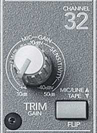
On this board, the line and mic inputs share a trim pot , which allows each individual channel to be balanced with the others regardless of differing input levels or microphone sensitivities. One level-setting strategy is to adjust the trims so that if the channel faders are set to the same value, all channels sound at equal strength. Since the trim pots control the channel's pre-amp, too high a setting may cause the channel to distort. Having a meter bridge or LED to warn you of a channel overload is helpful. The input overload LED will measure the input+preamp level regardless of the channel fader position, so it is really important to heed to avoid overload distortion. Often, these will have red, yellow and green LEDs—flickering green is good, it confirms you have signal, yellow OK for louder sections, red is bad for all but the more powerful transient sounds—means you need to trim the channel down or lower the strength of your input signal.
Some boards have a single XLR input for both line level devices and mics, and these all go through the channel's preamp. This is a common spot for distortion in the signal chain. Even at the lowest levels of preamp trim, the channel may still overload the preamp and distort. For this reason, channels are often supplied with a PAD switch that attenuates the input signal by up to 25 dB or more. It is not uncommon to need this pad for +4 dBu signals coming into your board from say a computer's audio interface. This module may also be supplied with a HPF (high pass filter, sometimes called low cut) that rolls off low frequencies in the rumble range, for example 80 Hz and below, helpful for mics when floor noise transmits up the mic stand or you have a foot tapper. The HPF may alternatively be found in the EQ section on some boards.
[On this Mackie board, the MIC/LINE-TAPE switch chooses whether the mic and line input OR the tape input is sent to the channel fader. The other input is then sent to a separate MIX-B output].
Channel Aux Sends
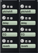
Digital Performer sends
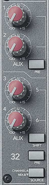
A mixer channel has an auxiliary set of outputs usually connected to effects devices such as a reverb box (some boards have internal effects which can also be feed by these outputs). For live performance, it is common to feed on-stage monitor speakers, return a mic feed to an on-stage laptop for live processing, or provide a signal to a video camera. For DAW virtual mixers (Digital Performer effect send section bottom image), these auxiliary channel outputs are used to send channel signals to digital signal processing plug-ins (such as reverb, delay, pitch change, EQ). Signals can be routed to these options from the effects sends, which are sometimes labeled aux sends or just aux. Boards typically have between two and six effect sends, often arranged in their own AUX section. Each channel can send its own relative strengths of the channel's input signal to one or more devices by adjusting the channel's effects send pots. Look elsewhere on the board for an effects send master, which must be turned up for any signal to be sent out of the board because it combines all the channel sends for that particular AUX SEND number. This is called a bus, because it is a common signal path that sums all of its individual contributors and allows an overall setting of their total strength. So while each channel send pot is designed to set the relative strength of the input signal, the overall strength can be conveniently controlled by the aux send master.
Example: You are mic'ing Peter, Paul and Mary with separate mics routed into separate input channels (CH)—CH 1, 2 and 3 respectively. You have the board's AUX 1 output routed to a reverb box. You desire a strong reverb on Peter, so you turn the CH 1 AUX 1 pot up to 12 O'Clock. You want less reverb on Paul, so you turn the CH 2 AUX 1 pot up to only 9 O'Clock. You want NO reverb on Mary, so you turn the Ch 3 AUX 1 pot down all the way. You find the AUX 1 MASTER on the board, and turn that up to adjust the overall reverb level. You are happy.
Finally, to complete an effects loop and allow the altered signal to be heard, determine how the effects devices are routed back to the board. Some studios route them back through effects returns, while most route them back through other board input channels. In this second method, it is possible to EQ and pan the returning signal differently from the original (a nice compositional idea). Additionally, it is possible to take a returning signal and send it to a second device. It is even possible to send an effect back into itself from the returning channel by carefully turning up the same aux send # pot on the return channel, creating a deliberate feedback loop. This was a key component of tape echo delay in early years, but can still be used, say, with delayed pitch change for an arpeggiated effect. WARNING: Do not send a returning effect signal back into the same effects bus if it has a short or no delay — this will produce an undesired feedback loop. Never send reverb back into itself as this will guarantee feedback.
The pre/post-fader button determines whether the signal sent from a channel will be altered by the channel fader. In pre-fader position, the signal is sent out at a strength determined only by the effects send pot and not affected by the channel fader. The pre-fader position is useful for techniques where you may wish to fade out the original signal, but still hear the altered sound. In post-fader position, both the effect send pot and the channel fader affect the overall strength of signal sent to the device. The post-fader position is useful if you wish both the original and effected sound to fade out completely when the channel fader is pulled down. The pre/post fader toggle in the pictured Digital Performer virtual board is the tiny 'P' button, along with the option to mute a send ('M').
