Chapter Two: Studio Gear
4. Mixing Consoles | Page 4
Input Channel Strips (continued)
Panning
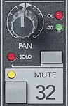
The pan pot controls the left/right or odd/even balance (see section below) of the channel's output. A stereo instrument coming into two board channels should be panned hard left on one channel and hard right on the other to maintain the maximum stereo effect. On the other hand, when planning the stereo image of a piece (which you should do!), placing mono sounds across the full range of the stereo field should be considered. Having mono sounds panned hard to one speaker or the other tends to make a listener aware of only two locations rather than a 180 degree soundfield and should be reserved for special circumstances. A pan pot on a stereo channel, which may be labeled alternatively as balance will actually attenuate one or the other input signals (L or R) when turned off of center.
The red OL (overload) light indicates that the channel's input is potentially distorting, because the input level is too high. The solution is to turn down the input sensitivity pot at the top of the channel. The green -20 dB light is a good indicator that signal is getting into the channel. The meter bridge, if set to monitor the channel input, not its output, is a more sophisticated tool for setting input sensitivity levels. The location of these input level LEDs varies widely by board. Some boards make it more possible to monitor the input on the meter bridge or LCD screen, but be cautious you are monitoring the channel's input level and not the channel output level. For line level devices, you may also need to use the channel pad if the OL LED is flashing, even with the channel input trim turned down all the way.
The mute button will silence the channel when activated, while the solo button will send the channel's signal to a separate solo bus, usually controlled by a solo master pot. On most boards, soloing a channel or channels will mute all other un-soloed channels—this can be tricky on digital boards that have multiple layers of inputs channels where the soloed channel may not be visible. Solo is designed to isolate sounds for actions such as EQ'ing, checking effect returns, or troubleshooting missing signals. Multiple channels may be soloed at the same time. Solo may, by default, put the channel's output into the headphone bus, but on newer boards, there are often options as to what the solo bus does.
The Channel Output Module
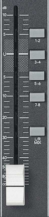
The channel output module controls the level and routing of the channel signal after it has gone through the input and EQ sections. Selector buttons allow a combination of routing. Buttons labels 1-2, 3-4, etc. route the signal to the board's eight group outputs, where they may be routed to separate speakers, or used to create a stereo mix in another board section. The master levels for group outputs are usually found as a separate bank of faders on the right side of the mixing console (see next page).
The Stereo or L-R selector routes the signal to the Left/Right or Stereo Mix output, usually controlled by a single master fader (color-coded red on Tascam digital boards) to the right of the group output faders. The Stereo bus would be used primarily in a two-channel listening environment, or with a headphone mixdown. It may be also to control sub levels, since the other eight channels are feeding the eight surround speakers.
The channel fader (the white vertical sliding tab) controls the level of output of the channel signal being routed into any of the master outputs selected and the level of signal to the effects sends if they are set to post-fader. These are usually calibrated in dB or VU (volume units). Faders are for the most part logarithmic, so they correspond with dB and the way we hear. If they were linear, as the fader were steadily lowered, the rate of the fade would be slower and slower in our perception.
The U stands for unity gain, the level at which the signal reaches the fader. 0 dB or 0 VU is designed to equal a gain of +4 dBu, which as mentioned earlier, corresponds to pro gear line level. Above the U, additional strength (positive gain) is added to the signal. It is important to watch your channel meters when adding gain, because if a signal comes into the channel at 100% or you add additional energy through EQ, more than likely, you channel output will clip and distort. Remember, approximately every 6 dB is a doubling of amplitude. Below unity should be marked as negative dB, all the way down to -infinity (∞) or silence.
Some boards include a PFL or pre-fader listen button in this section to allow auditioning the channel signal, normally post-EQ, but at full level, not attenuated or boosted by the channel fader. This is really helpful in live-sound reinforcement situations where one might want to monitor the incoming signal on headphones, but not disturb the pre-set fader level. PFL is most often routed to the monitor bus by default, but BE CAREFUL when enabling PFL if the channel is routed to speakers, as it may be. Boards like the Yamaha 01v96 don't have a PFL button, but allow the solo button to act as PFL when choosing pre-fader on the solo setup page.
