PLAY ALONG: Download the VCV Rack Sub-audio Rate FM Modulation Patch example. Once downloaded, fire up VCV Rack and use the File-Open menu command to open it, or you may get an error message if you double-click on the file itself. If you haven't yet downloaded the free VCV Rack app, click here for information.
Chapter Four: Synthesis

7. Patches: Sub-audio Rate Modulation | Page 2
Sub-audio Rate Modulation Patches (click on synths for enlarged images in a new window):
Sub-audio Rate Frequency Modulation Patch (Vibrato)
click on synth for enlarged image in a new window
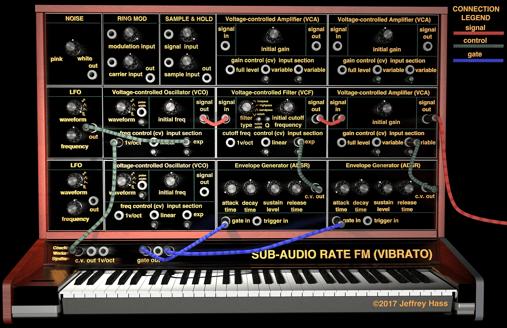
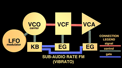
Sub-audio Rate Frequeny Modulation Patch Breakdown
Connections:
Signal Path: VCO signal output→VCF signal input; VCF signal output→VCA signal input; VCA signal output→to board/amp/speakers.
Control Path: LFO→VCO exponential c.v. input; KB c.v. output→KB 1 V/oct c.v. input; Envelope Generator(EG)1→filter cutoff frequency c.v. input; EG2→amplifier gain c.v. input.
Gate Path: KB gate output to both EG's.
When a violinist rolls their fingers back and forth longitudinally on a string, it produces and rise and fall in frequency called vibrato. This is the effect attaching a modulating oscillator to the frequency control input of the audio-rate VCO of a patch has. As the modulator's output voltage rises and falls, so too does the pitch of the signal-producing oscillator that we ultimately hear, which is called the carrier oscillator. Note that the patchcord from the modulating oscillator to the VCO frequency control input is green, indicating its signal being used as a control voltage source—not heard directly as audio; only its effect on the signal oscillator's frequency is heard.
Parameters for the modulation include:
- The waveshape of the modulating oscillator. A sine or triangle wave would produced the traditional smooth up and down vibrato, while a pulse wave would produce a trill, and a sawtooth wave would produce a ramp up or a ramp down.
- The frequency of the modulating oscillator would control the speed of the vibrato.
- The depth of the modulation, or how far off center pitch is the carrier oscillator pushed by the moulting voltage. This is normally controlled by the attenuator knob next to the carrier VCO's c.v. input. The less of the modulating voltage allowed into the module, the less its effect of shifting the pitch and the smaller the musical interval of modulation. On modern keyboard synths, the depth of modulation is usually controlled by the mod wheel.
- Whether the LFO is outputting a unipolar or bipolar waveform. If unipolar (0 V and above), the modulating pitch will only rise from the carrier's initial frequency. If bipolar (for example, -5 to +5 V), the modulating pitch will gravitate above and below the carrier's initial frequency. If connected to the linear frequency control input, the modulation will rise and fall an equal number of Hz, if connected to the exponential frequency control input, the modulation will rise and fall an equal musical interval.
- The modulating wave is often summed with a second c.v. source. In this case, the keyboard voltage is also connected to a frequency control input on the VCO carrier, so with each different key, there is vibrato around the keyboard's center pitch.
