Chapter Four: Synthesis
7. Patches: Sub-audio Rate Modulation | Page 3
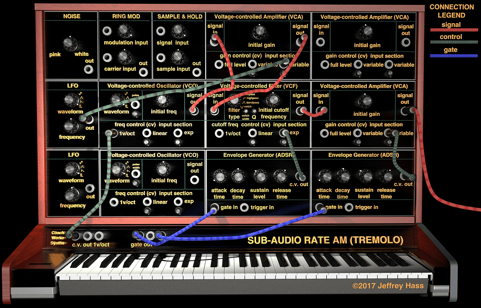
Sub-audio Rate Amplitude Modulation Patch (Tremolo)
click on synth for enlarged image in a new window
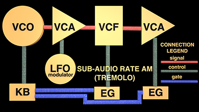
Sub-audio Rate Amplitude Modulation Patch Breakdown
Connections:
Signal Path: VCO signal output→VCA1 signal input; VCA1 signal output→VCF signal input; VCF signal output→VCA2 signal input; VCA2 signal output→to board/amp/speakers.
Control Path: LFO→VCA1 c.v. gain input; KB c.v. output→KB 1 V/oct c.v. input; Envelope Generator(EG)1→filter cutoff frequency c.v. input; EG2→VCA2 c.v. gain input.
Gate Path: KB gate output to both EG's.
When a violinist rapidly alternates bow direction on a string it is called tremolo. It causes the amplitude or gain of the sound to rapidly change. This is exactly what sub-audio rate amplitude modulation does. In the patch above, note that there are two VCA's. The final amplifier in the patch acts as normal, beginning and ending the note with the envelope generator. The amplifier between the VCO and VCF, however, is the one being modulated to produce tremolo. And the reason for this is so the modulating voltage does not put the final VCA into the audible range even after the note has stopped. Or conversely, to keep the note from cycling below audible range on the troughs of the modulating waves.
Normally, tremolo is created with a unipolar modulating signal, so the note is not pulsed on and off as the modulating wave goes below 0 V. This can also be accomplished by raising the modulation VCA's initial gain offset while simultaneously attenuating the incoming modulating c.v.. A sine or triangle wave would give a traditional tremolo effect. However, if a techno-style pulsed sound is what one is after, then a bipolar wave can be used, and a downward sawtooth wave or pulse wave would be ideal.
Parameters for the modulation include:
- The waveshape of the modulating oscillator, as just mentioned.
- The frequency of the modulating oscillator would control the speed of the tremolo.
- The depth of the modulation, or how much of a change in amplitude is caused by the oscillations of the modulator's voltage. This is normally controlled by the attenuator knob next to the VCA's c.v. input. The less of the modulating voltage allowed into the module, the less its effect of changing the amplitude and the smaller the effect. On modern keyboard synths, the depth of modulation is usually controlled by the mod wheel, which is usually either routed either for frequency or amplitude modulation by default in the patch programming.
PLAY ALONG: Download the VCV Rack Sub-audio Rate AM Modulation Patch example. Once downloaded, fire up VCV Rack and use the File-Open menu command to open it, or you may get an error message if you double-click on the file itself. If you haven't yet downloaded the free VCV Rack app, click here for information.
