Chapter Four: Synthesis
7. Patches: Sub-audio Rate Modulation | Page 4
Sample and Hold
If you have ever watched a 60's or 70's film with a mainframe computer or spaceship computer calculating something, indicator lights flashing, chances are you have heard the fast, random pitch sequence that so often accompanies them in the soundtrack. More than likely, those sounds were produced with a sample and hold synthesis module. Classic modular synths, and even current softsynths often contain a sample and hold (S&H) module. In most cases, the module itself does not produce an audio signal, but instead outputs control voltage that can be applied to modulate anything that accepts c.v., such as a VCO pitch or phase width input, a filter c.o.f., an amplifier, or even the frequency of another modulator for a very cool form of double modulation.
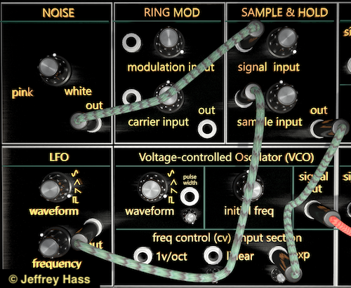
The sample and hold module does basically what its name says it does. It takes sequential snapshots or samples of the instantaneous amplitude (as a voltage level) of an incoming signal and holds and outputs each successive voltage until the next snapshot is taken. In most cases, an LFO or noise source is patched into the signal input of the S&H module to then be have its voltage sampled. Sampling noise will produce a succession of random voltages, with white noise producing voltages equally across the spectrum, and pink noise statistically generating fewer higher voltages. An S&H patch using noise as the signal source is picture below.
When the module's c.v. output is applied to the frequency control input of a carrier VCO, sampling noise is what gives the classic 60's-70's sample and hold pitch sequence. However, if a periodic waveform from an oscillator is used for the signal input, then the signal's waveshape may determine the shape of the output. For example, using a triangle wave might yield an upwards and downwards arpeggio or scale when applied to a carrier oscillator, while a sawtooth wave would generate a scale only up or down. A sine wave would have similar scales, but its rounding would cause the change in pitch to become more compressed towards the waveform's peaks. And basically, a square wave is just plain boring to sample, as it will only yield one voltage or another.
The second input of the S&H module is for the sample input. Since this module acts very much like a digital-to-analog converter, one might consider this to be the clock or trigger input. Most often a pulse wave (see patch image above), or other wave peak (for example from a downward sawtooth wave) from an LFO, or (rarely) even noise or an external audio signal will trigger the module to take a snapshot and then hold the instantaneous amplitude of the signal input until the next trigger. If using an LFO, the frequency of the sample LFO determines the frequency of c.v. change. The most oft-used frequency adjustment between a signal input LFO and a sample input LFO is that the sample LFO has a lower frequency, but that is not a rule, and having a faster sample LFO than signal LFO may generate a quasi-random succession of c.v.'s.
For periodic waves, if the ratio of the signal frequency to sample frequency is 1:n, whereby n is an integer, then the output of the S&H will have a steady repeating pattern. However, if n is not an integer, then the pattern will shift in phase with very interesting results.
The video example below has a 1:8 signal-to-sample frequency ratio, so it creates a steady non-offset scale or arpeggio. The intervalic width of the steps (you may hear that it is microtonal) is controlled by the attenuator of the carrier VCO the S&H module is attached to. The more of the S&H voltage allowed in, the wider the intervals will be. In the video example, the signal input is an upwards sawtooth wave in red, the sample input trigger waveform is the pulse wave in blue, and the resulting sample and hold c.v. that will be output from the module is in orange.
The table below contains various examples produced by sample and hold. The ratios listed are the signal input frequency to sample input frequency. In all examples, the c.v. output of the Sample and Hold module is routed to the frequency control input of a carrier VCO. |
|
|---|---|
| Parameter Description | Audio Example |
| Down sawtooth signal input, with a ratio of 1:4.16. Note the rising downward scalar pattern that repeats approximately ever 4 cycles of the signal input. | |
| Triangle signal input with a ratio of 1:1.6. Note the pattern overshoots the shape of the triangle wave and catches various phase points, but still creates a consistent repeating pattern. | |
| Down sawtooth with an increasing frequency of the sample input. Note how the more rapid the trigger becomes, the smaller the successive intervals become. | |
| White noise signal input, with a little ring modulation added to the carrier to recreate the filmic computation sounds of the 60's. | |
PLAY ALONG: If you haven't yet downloaded the free VCV Rack app, click here for information. This example requires the installation of the free BOGAUDIO modules. Open Rack and click on Library→Manage Plugins and navigate to BOGAUDIO library, then install.
Download the VCV Rack Sample and Hold example. Once downloaded, fire up VCV Rack and use the File-Open menu command to open it, or you may get an error message if you double-click on the file itself.
