Chapter Four: Synthesis
14. A Digital Synthesis Language Sampler | Page 11
Max
Max, previously known as Max, Max/MSP, Max/MSP/Jitter, and named in honor of Max Mathews, is an application that is currently developed and sold by Cycling ’74 of San Francisco. In its current state, it is a graphic programming language for the creation of sound, visuals and even autonomous control of external devices for things like multimedia installations. Its strong suit has always been in its ability to respond interactively with its own algorithmic processes set up by a composer or artist, or to respond to external data input via incoming audio or controller information from a performer. It has assisted many composers in moving beyond instrument+fixed tape pieces by allowing them to design patches that respond flexibly and interactively to the musician’s input. Many 3d-party authors and institutions have added to Max’s extensive library of objects. A fully working and editable version of Max can be downloaded from here, but a purchase is necessary to save changes. Cycling '74 is fantastic about providing special discounts to students and educators.
History
Max has a long and varied history dating back to 1985, when American software designer Miller Puckette created an early version at IRCAM in Paris. The software created interactive graphic scores on the Macintosh that, though they did not produce sound themselves, sent control signals via MIDI or other protocols to synths, and eventually to the large IRCAM Sogitec 4X audio computer for digital signal processing a few years later.
Toward the end of the 1980’s, IRCAM had created Max/FTS that ran on the Institute’s more compact ISPW. Opcode released the first commercial Max version, with expansion by Dave Zicarelli in 1990. It originally featured only MIDI I/O and data processing, but was later expanded to include audio and called Max/MSP, as Zicarelli bought the rights from Opcode and started Cycling ’74. Max 4 added video with the Jitter objects extension. In 2017, Ableton bought Cyling, allowing user-created Max modules to be used in its flagship app, Ableton Live.
Features
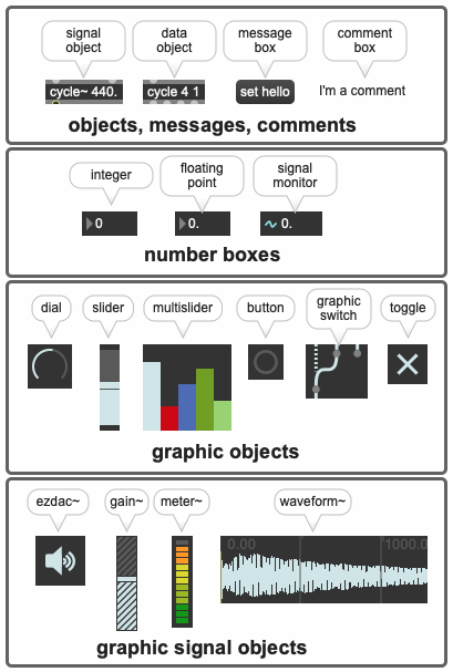
Max is a graphic music programming environment built around objects a user “patches” together, similar to the analog synthesis days of modules and patch cords. A typical Max composition is comprised of one or more Max patchers, the window or windows that make up the performance interface that contain the Max objects. Max graphic objects may include additional text inside there boundaries, send or receive text-based data, or indeed refer to an external or internal text file or script. Below is an image of some of the many available Max graphic components. Note that audio-based objects include a tilde (~), while data-based, control rate objects do not.
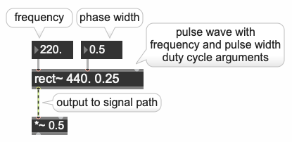
A Max object (inserted by pressing the letter n then typing the desired object's name inside the box, or using the interface’s object list around the window edges), may also take inline arguments which set the initial values for the object. In addition, Max objects have inlets and outlets (represented by small dots above and below respectively) that allow fixed or changing values to be input from other objects, and the results sent out the outlets. Objects are connected by clicking, then dragging patch cords from outlets of one object to inlets of another. If it is an “illegal” connection, the cord won’t connect. Hovering a mouse cursor over these inlet/outlet dots will give popup hints as to what they do. Expanding the Max patcher window by clicking on the i icon on the right side, an Inspector will also be opened that allows for additional object qualities to be added or modified. Right-clicking on the object will bring up a working help window, often placing the object in a working patch that can be copied and pasted directly into your patch. The rect~ pulsewave object with both internal arguments and external inputs is pictured here.
Around 2018, mc extensions were added to existing Max objects, allowing them to process and produce multiple channels of audio from a single object. For example, a single mc oscillator object could output an array of multiple pitches. In addition, the gen~ object was added to allow the use of low-level native audio signal processing routines of extremely high efficiency akin to the assembly code routines that remained in Music V.
Sample Patching with Explanation
Max programming is done within an IDE environment called a patcher window. The window, as mentioned, contains additional icons around its periphery that provide access to categorized objects, the Inspector, visual presentation modes, overall audio level, lock/unlock for programming, audio on/off with levels and much more. The patcher window is pictured below (mobile users slide image right), in edit mode for programming (the bottom-left lock icon is unlocked) with the right-hand Inspector for adjusting the selected multislider parameters displayed.
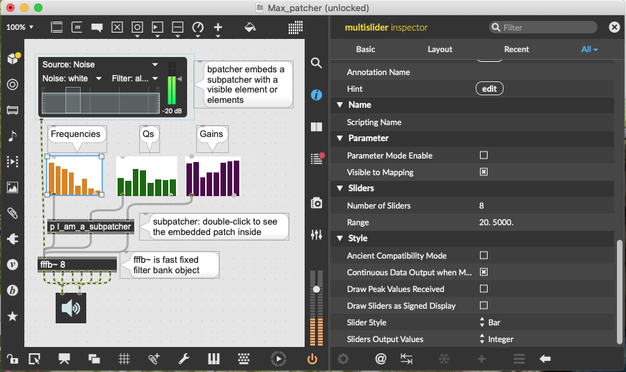
This particular patcher, featuring a noise source feeding a multiband filter bank (fffb~), also contains a bpatcher and a subpatcher, which represent patchers within patchers to help keep the complexity of the main patcher manageable. Note that control-rate data patch cords are a solid color, while audio-rate signal connections are striped. The signal path of the patcher ends in a graphic stereo DAC output called an ezdac. Finally, for concert performance, a Presentation mode may be created that hides all but the most important positionally-arranged elements a performer needs to see when the patcher is locked and placed in that mode by clicking on the TV icon at the bottom of the window.
A more advanced patcher (a video with the patcher’s audio output, click image to play) is provided below with brief annotations about its function. The patcher is designed to alternate between playing 21 scalar pitches and 21 random pitches via a sawtooth oscillator. The oscillator’s output is passed through an envelope-controlled resonant bandpass filter followed by an envelope-controlled amplifier/attenuator similar to the basic patch of the prior analog synthesis page.
click video image below to play/pause
1–the toggle object alternates between outputting a 1 (on)and 0 (off) when clicked or when it receives a zero (off) or non-zero (on) input. In this case, clicking on the toggle both starts and stops the metronome object below AND turns the patcher’s audio DAC on and off.
2–the metro object outputs a bang, essentially a trigger at intervals set in millisecond in the object’s argument, in this case every 150 milliseconds. The integer box attached to it can override the millisecond argument with new values. The metro object in this patch is performing four functions, discussed below.
3–the button object provides a visual reference to the bangs being generated by the metro above, although it is not strictly necessary and could be bypassed. But it looks cool and confirms the metro is on or off.
4–the counter object outputs integers sequentially from 0 to 20, one integer per bang (trigger) it receives from the metro/button objects, patched into its leftmost inlet. When it reaches 20, it loops back to 0 on the next bang. The output values are displayed by the integer box object below. The integers being output perform two functions. To the right, they are used to switch between stepwise and random pitches (more on this below in #6). To the left, when they are routed through the graphic switch, they are multiplied by two [* 2] and then incremented by 40 [+ 40] to put them in a good MIDI note number range to drive the scales and the oscillator frequency.
5–the random number generator output an integer value between 0 and one less than 20. Like the counter object, it outputs the next value with each bang from the metro and button. When routed through the graphic switch, its integers are also multiplied and added to drive the oscillator frequency.
6–the objects that comprise 6 (6a,6b,6c) switch between driving the oscillator frequency from the sequential counter values and driving the oscillator frequency from the random object. Each time the counter reaches 20, a sel object (short for select) with an argument of 20 (6a) sends out a bang and flips the toggle (6b) state. The toggle state of 0 or 1 in turn causes the graphic switch called a gswitch (6c) to alternate between accepting scalar input from the counter (toggle 0 value) and random input from the random object (toggle 1 value). Because it is graphic, you can see it switch.
7–after the math above that places the counter or random values in a comfortable range, the mtof object, short for MIDI-to-frequency, converts the incoming MIDI note numbers into their appropriate cps frequencies for use by the oscillator below.
8–the sawtooth oscillator that is creating the audio of the patch. Note the frequency input is a solid data, control-rate patch cord, but the output patch cord is striped, indicating that it is an audio-rate signal.
9–the line~ object produces a segmented stream of output values akin to an envelope generator. The message box connected to it provides the target values and timing. The format for that is a little unusual in that the first number is the initial starting value, followed by a comma, then the first target value followed by the time to reach it in milliseconds. In this case, line~ will output a ramp from 200 to 1000 over a span of 100 ms. The message box is triggered to send this envelope information to line~ when it receives a bang from the metro, which is every 150 ms.
10–a resonant bandpass filter whose internal initial arguments are gain (1. Is full), center frequency (200) and Q (5). Incoming signal is left-most input, center frequency sweep input is being driven by line~. The other arguments are not modified by inputs, although they could be.
11–a line~/message box being used for amplitude envelope below. Same sort of ramp message as 9 being banged by the metro for each pulse going from 0 to 1 in 100 ms, but in this case, there is a second segment that will return the amplitude to 0 in another 50 ms.
12–this innocuous *~ multiply object is one of the most frequently used to control signal amplitudes throughout patchers, either multiplying two signals, or a signal and a static or changing second input value. Oscillators put out full-scale digital signals (equivalent to 1 to -1). Multiplying them by a scaling factor of 1. or less attenuates them. So in this patch, the *~ object is acting like a VCA, receiving envelope data from the attached line~ object. Multiplying full-scale signals by values greater than 1. will cause clipping in many circumstances.
13–the gain~ or live.gain~ object adds a second layer of overall gain control to the patch. Without it, the peak amplitude would be solely controlled by the *~ object above. Numerous signals can be simultaneously patched into the gain~ object, which would then act as a gain master. The live.gain~ object is nice in that it not only has a slider, but also a signal level meter. It was designed to function in a Max-for-Live patch that can be used in Ableton Live.
14–the graphic stereo ezdac~ is the patch’s audio on/off button and routes any signal input to Max’s designated output device (chosen in the Options-Audio Status program menu). It can either be switched on and off by clicking on it with the mouse cursor, or in this case, it is activated/deactivated by the same toggle above that turns on the metro object. It is best practice to have only ONE ezdac~ per composition and route everything through it, though Max will allow you to have many ezdacs in subpatchers and elsewhere if you ignore this advice. Turning on one turns them all on. If one wishes to have more than two output channels, there is a non-graphic dac~ object that can handle as many channels as you have audio hardware to handle (up to 1024!).
This patch can be downloaded from here, and used and changed with the free download of Max.
As mentioned earlier in this section, the information above only scratches the surface of what Max can do and is provided to encourage further inquiry using the resources below.
Resources
Cycling ‘74
Max downloads and purchase, help, downloadable series of tutorials
Book: Electronic Music and Sound Design : Theory and Practice with Max 8 - Volume 1 and 2 (Fourth Edition)
Alessandro Cipriani and Maurizio Giri
Dude837: Extensive beginner to advanced Max Youtube tutorials by Sam Tarakajian
